
Related Manuals for Grin Technologies Frankenrunner

Summary of Contents for Grin Technologies Frankenrunner
- Page 1 Frankenrunner User Manual Rev 1.0 The Frankenrunner Motor Controller User Manual – Rev 1.0 Grin Technologies Ltd Vancouver, BC, Canada (604) 569-0902 email: info@ebikes.ca web: www.ebikes.ca Copyright © 2022...
-
Page 2: Table Of Contents
Frankenrunner User Manual Rev 1.0 Table of Contents 1 Introduction.................1 2 Connectors................2 2.1 Battery Power....................2 2.2 Motor Cable – L10 Model................2 2.3 Motor Cable – MT Model................3 2.4 Cycle Analyst WP8 Plug.................3 2.5 Mains Signals Plug..................4 2.6 PAS / Torque Plug...................4 2.7 Communication Port..................4... -
Page 3: Introduction
Sensorless operation with high eRPM motors Unlike standard trapezoidal or sine wave controllers, the Frankenrunner is a field oriented controller that must be tuned to your motor, battery, and performance requirements for proper operation. This process is detailed in Section 5... -
Page 4: Connectors
Frankenrunner User Manual Rev 1.0 2 Connectors The controller has been connectorized to achieve maximum versatility with minimal wiring, using a combination of waterproof overmolded ebike plugs for signals and popular compact connectors for high current. 2.1 Battery Power The embedded plug on the back of the device provides a reliable hookup to DC battery power through the compact and popular XT60 plug interface. -
Page 5: Motor Cable - Mt Model
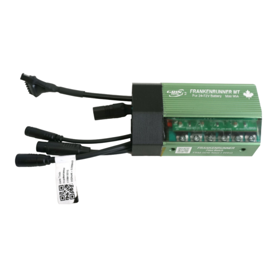
Frankenrunner User Manual Rev 1.0 2.3 Motor Cable – MT Model The motor connection on the MT model uses an MT60 plug for the 3 phase power, and both 5 pin and 2 pin JST-SM plugs for Hall sensor and temp/speed signals. -
Page 6: Mains Signals Plug
Frankenrunner User Manual Rev 1.0 2.5 Mains Signals Plug An alternate interface is provided via the 9 pin Mains cable. This uses uses the Signal D 1109 Connector from Cusmade, and supports conventional ebike wiring strategies for 3 party display consoles. It shares many signals with the... -
Page 7: Wiring Strategies
Micro USB or USB-C port. 3 Wiring Strategies The Frankenrunner can be hooked up to the controls of an ebike system in one of three ways. It can be connected under the full control of a V3 Cycle Analyst, under the control of a 3 party display, or “headless”... -
Page 8: Headless System
3.3 Headless System Finally, the Frankenrunner can be run with only a throttle on the Mains plug, or a PAS / Torque sensor plugged into the 6 pin PAS plug. In these arrangements, it is essential to wire up the on/off power switch on either the WP8 plug or the... -
Page 9: Controller Mounting
5 Parameter Tuning If you purchased the Frankenrunner as part of a complete conversion kit that includes a battery, a motor, and so on, the controller should be pre-configured and no tuning of the parameters should be necessary. This section can be skipped entirely. -
Page 10: Importing Default Motor Parameters
With the Frankenrunner powered on, plug in the TTL->USB cable from your computer to the device. After launching the Phaserunner software, select the COM port associated with the USB cable and you should see “Frankenrunner is connected” on the top. -
Page 11: Motor Autotune
Frankenrunner User Manual Rev 1.0 Install these new settings to the Frankenrunner via the “Save Parameters” button. Apply some throttle and your motor should run smoothly. If it does, you can now skip over the “Motor Autotune” section, and continue with “Battery Limits.”... - Page 12 The effective pole pairs is a count of how many electrical cycles corresponds to one mechanical revolution of the motor and must be set correctly. The Frankenrunner needs this information to correlate it’s electrical output frequency with the wheel speed. In a direct drive (DD) motor, it is the number of magnet pairs in the rotor, while in a geared motor you need to multiply the magnet pairs by its gear ratio.
- Page 13 “Flip Motor Spin Direction on Next Autotuning?” and relaunch the “Spinning Motor Test.” During the spinning test, the Frankenrunner will start the motor in sensorless mode. If the motor fails to spin and just starts and stutters a few times, adjust the sensorless starting parameters as described in section 5.5, “Tuning the...
- Page 14 Frankenrunner User Manual Rev 1.0 -12-...
-
Page 15: Battery Limits
In addition to regulating the current flowing in and out of the battery pack, the Frankenrunner can independently control the maximum phase currents that flow to and from the motor. It is the motor phase current that both generates torque... - Page 16 Frankenrunner User Manual Rev 1.0 and causes the motor windings to heat up. At low motor speeds this phase current can be several times higher than the battery current you see on a Cycle Analyst. The “Max Power Limit” sets an upper limit on the total watts that will be allowed to flow into the hub motor.
-
Page 17: Tuning The Sensorless Self Start
Frankenrunner User Manual Rev 1.0 5.5 Tuning the Sensorless Self Start Advanced Setup If you are running in sensorless mode, then you may need to tweak the sensorless self start behaviour. When a brushless motor is run without Hall sensors and started from a complete stop, the motor controller attempts to ramp up the motor’s rpm... -
Page 18: Throttle And Regen Voltage Maps
Advanced Setup tab With most ebike controllers, the throttle signal controls the effective voltage and hence unloaded rpm of the motor. With a Frankenrunner, however, the throttle is directly controlling the motor torque. If you pick the motor off the ground and give it just a tiny amount of throttle, it will still spin up to full rpm as there is no load on the motor. -
Page 19: Field Weakening For Speed Boost
5.7 Field Weakening for Speed Boost Basic Setup tab The Frankenrunner can boost the top speed of your motor beyond what is normally possible from your battery voltage. This is accomplished by injecting a field weakening current in advance of the torque producing current. -
Page 20: Virtual Electronic Freewheeling
5.8 Virtual Electronic Freewheeling Dashboard/Basic Setup tabs The Frankenrunner controller can be set to inject a small amount of current into the motor, even when the throttle is off. When properly tuned, this current injection can overcome the drag torque present in hub motors capable of regenerative braking, allowing them to spin freely when pedaling without any throttle. -
Page 21: Additional Details
6 Additional Details: 6.1 Signal Mapping The Frankenrunner uses the analog Brake 1 signal input as both the throttle and regenerative brake signal source. This differs from the earlier Phaserunner controllers which used separate signals for “Throttle Sensor Source” and “Regen Brake Source”, which were then shorted externally in the connector wiring. -
Page 22: Reverse Mode
These changes were necessary to fully support the independent use of torque sensors and throttles on the same controller. As a result if full parameter settings saved from a Phaserunner device are then imported to the Frankenrunner or vice versa, unexpected throttle and braking behavior can occur. -
Page 23: Combined Temp / Speed Signal
If there are no speed pulses present on the Wheel Speed signal, and the temperature signal periodically drops to 0V, then the Frankenrunner will treat those 0V pulses as speed signals to track wheel rotation. -
Page 24: Cycle Analyst Settings
7 Cycle Analyst Settings Current Sensing [ Cal->RShunt ] The Frankenrunner uses a 1.00 mW +- 0.02 mW shunt resistor for current sensing. The exact calibrated value is laser engraved on the controller heatsink. In order to have the most accurate readout of battery current, ensure that the Cycle Analyst’s “RShunt”... -
Page 25: Led Flash Codes
Frankenrunner User Manual Rev 1.0 8 LED Flash Codes The embedded red LED inside the controller provides a useful status indicator. It will flash according to the following table if the controller detects any faults. Some faults will clear automatically once the condition clears, such as “Throttle Voltage Outside of Range,”... - Page 26 Frankenrunner User Manual Rev 1.0 The LED may also flash several different warning codes. These warnings do not stop the controller from running and will appear as various limits are reached in normal operation, they are not usually a cause for any concern.
-
Page 27: Specifications
Frankenrunner User Manual Rev 1.0 9 Specifications 9.1.1 Electrical Peak Battery Current Programmable up to 96A* Peak Phase Current Programmable up to 96A* Peak Regen Phase Current Programmable up to 96A* Continuous Phase Current Approximately 55A at thermal rollback, varies with air...
Need help?
Do you have a question about the Frankenrunner and is the answer not in the manual?
Questions and answers