Advertisement
Quick Links
Advertisement

Summary of Contents for GS UNDERFLOOR HEATING ETO2
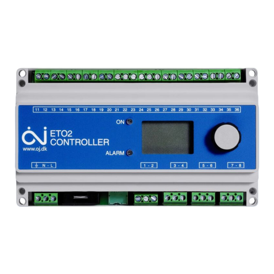
- Page 1 Type ETO2 Controller for ice and snow melting...
- Page 2 Type ETO2 improper use of this device, may cause an installer to Type ETO2 is an electronic controller for fully automatic, commit errors, that may lead to ice & snow conditions economical ice and snow melting on outdoor areas and in resulting in serious injury or death.
-
Page 3: Applied Standards
On/off differential ..... .0.6°F / 0.3°C ETO2-4550-EU28: CE marking LVD/EMC: EN60730-2-9 Temperature range ....-4/+50°F / -20/+10°C ETO2-4550-US28: CAN/CSA E 60730-2-9:01. -
Page 4: Sensor Installation
ETO2 Gutter sensor type ETOR-55: SENSOR INSTALLATION Designed to be mounted in gutter or downpipe. Is used together with outdoor sensor type ETF. Ground sensor ETOG, fig. 1+3: For installation on outdoor areas where snow and ice is a Detection ....... .Moisture Mounting . - Page 5 Connect 1 ETF sensor to terminals 31-32. Connect heating cable to output relays 1, 2 and 3 ETO2 installation according to g. 8. The unit is intended to be DIN-rail mounted in an approved panel.
- Page 6 ETO2 • 2-zone electric heating control with ETOG (fig. 6): • 1-zone electric heating control and output control Connect 2 ETOG sensors to terminals 11-20. (Y/∆) (fig. 9+10): Connect heating cable for zone 1 to output relay 1 Advanced 2-step control with ETOG-55. 1/3 power on heating cables in afterrun.
- Page 7 3. The output relay for the heating cable in the zone control, see User Manual, Startup. concerned should activate and ON should be indicated on the ETO2 display. Check that the • Remote control (fig. 15): heating cable becomes warm, check the voltage if The forced heat and standby functions can be remotely possible.
- Page 8 ETO2 WIRING Terminal Colour code Wiring N, L Supply voltage, 120-240 V AC 50/60 Hz 1, 2 Alarm relay (potential free) max. 5 A 3, 4 Output relay 1, 16 A (potential free), Heating cable 1 (zone 1) / Primary pump...
- Page 9 ETO2 Terminal Colour code Wiring 27, 28 Supply water temperature sensor, ETF-1899A 29, 30 Return water temperature sensor, ETF-1899A 31, 32 Outdoor temperature sensor, ETF 33, 34 Standby, external input 35, 36 Forced control heat, external input...
-
Page 10: Product Disposal
Fig. 11 Hydronic heating with mixing valve Fig. 12 Simple hydronic application Fig. 13 Hydronic mixing valve connection Fig. 14 Hydronic pump connection Fig. 15 Connections for remote control of standby and forced heat Fig. 16 ETO2 controller, terminal overview... - Page 11 ETO2 Fig. 1 ETOG-55 Installation Fig. 2 ETOR-55 Installation...
- Page 12 ETO2 Fig. 4 Electric 1-zone with ETOR-55 / ETF Fig. 3 Electric 1-zone with ETOG-55 sensor...
- Page 13 ETO2 Fig. 6 ETOG-55 connections Fig. 5 Electric 2-zone with ETOG, ETOR and ETF...
- Page 14 ETO2 Fig. 8 Electric heating cable connections Fig. 7 ETOR-55 connections...
- Page 15 ETO2 Fig. 9 Advanced 2-step with ETOG-55. 1/3 power on Fig. 10 Advanced 2-step connections. 1/3 power on heating cables in afterrun. heating cables in afterrun.
- Page 16 ETO2 Fig. 12 Hydronic, simple application Fig. 11 Hydronic heating with mixing valve...
- Page 17 ETO2 Fig. 14 Hydronic pump connection Fig. 13 Hydronic mixing valve connection...
- Page 18 ETO2 Fig. 15 Connection of Stand by & forced heat FORCED CONTROL HEAT...
- Page 19 ETO2 Fig. 16 01923 249026 07941 169635 www.gs-ufh.co.uk gs@warmfloors.co.uk GS UNDERFLOOR HE ATING LTD. 14 The Gateway – London – WD18 7HW...
Need help?
Do you have a question about the ETO2 and is the answer not in the manual?
Questions and answers