
Summary of Contents for Advanced Energy Industries AMN PS-2A
- Page 1 sales@artisantg.com artisantg.com (217) 352-9330 | Visit our website - Click HERE...
- Page 2 U S ER MANUAL AMN PS-2A Automatic Matching Network Power Supply Controller 5708577-A April 17, 2002 Advanced Energy Industries, Inc. 1625 Sharp Point Drive Fort Collins, CO 80525 USA 970.221.4670 technical.support@aei.com...
- Page 4 User Manual AMN PS-2A Automatic Matching Network Power Supply Controller 5708577-A...
- Page 5 This manual and the information contained herein is the property of Advanced Energy Industries, Inc. No part of this manual may be reproduced or copied without the express written permission of Advanced Energy Industries, Inc. Any unauthorized use of this manual © or its contents is strictly prohibited. Copyright 2000 Advanced Energy Industries, Inc.
- Page 6 AMN PS-2A TRADEMARKS is a registered trademark of Advanced Energy Industries, Inc. Advanced Energy is a registered trademark of Advanced Energy Industries, Inc. AE is a registered trademark of Advanced Energy Industries, Inc. 5708577-A...
- Page 7 ® Advanced Energy 5708577-A...
-
Page 8: Table Of Contents
AMN PS-2A Table of Contents Chapter 1. Introduction Read This Section! ..........1-1 Interpreting the Manual . - Page 9 ® Advanced Energy Chapter 5. Installation, Setup, and Operation Installing ............5-1 Unpacking .
- Page 10 AMN PS-2A Controller Front Panel ........
- Page 11 ® Advanced Energy 5708577-A...
- Page 12 AMN PS-2A List of Tables Electromagnetic Compatibility (EMC) ........1-3 Safety .
- Page 13 ® Advanced Energy 5708577-A...
-
Page 14: Chapter 1. Introduction
AMN PS-2A Chapter Chapter Introduction READ THIS SECTION! To ensure safe operation, you should read and understand this manual before you attempt to install or operate this unit. At a minimum, read and heed the “Safety” section in this chapter. - Page 15 ® Advanced Energy This box identifies hazards or unsafe practices that could result in personal injury. This box identifies hazards or unsafe practices that could result in product or property damage. The following symbols could appear on labels on your unit. Hazardous Voltage High voltage CE label...
-
Page 16: Safety
AMN PS-2A SAFETY Do not attempt to install or operate this equipment if you have not first acquired proper training. • Ensure that this unit is properly grounded. • Ensure that all cables are properly connected. • Verify that input line voltage and current capacity are within specifications before turning on the power supplies. -
Page 17: Certification
® Advanced Energy This device must be installed and used only in compliance with the standards listed and applicable requirements. Certification Certain options of this product are certified by: • CE marking is self addressed by AE Compliance Engineering • EMC measurements verified by UNISYS PCTC. For more information, refer to the letter of conformance (US) or declaration of conformity (EU) accompanying the product. - Page 18 AMN PS-2A • For units with captive line cord, you must install and operate this device with a disconnect switch that conforms to the applicable requirements. The switch must be easily accessible and near the device. • Install this device so that the input power connection is inaccessible to the user •...
- Page 19 ® Advanced Energy 5708577-A...
-
Page 20: Chapter 2. Theory
14 (+12 Vdc) and 15 (ground) of the matching network connector (J1). The indicators and meters on the front panel of the AMN PS-2A allow the user to monitor controller status information, including: • Power on/off •... -
Page 21: Theory Of Operation
The phase/magnitude detector in the matching network samples the transmission line at 50 Ω and generates error signals, which are then sent to the AMN PS-2A. These signals cause the servomotors to turn the series and shunt capacitors. The direction of change depends on the polarity of the error signals. - Page 22 If the comparators receive no signals from these sensors, the FAIL LED on the front panel of the AMN PS-2A controller lights. To prevent damage to the series and shunt capacitors, the position fail detector also feeds the limit detector, which activates the brake that stops the servomotors when a limit is exceeded.
- Page 23 ® Advanced Energy 5708577-A...
-
Page 24: Chapter 3. Specifications
The sections in this chapter describe the specifications of this unit, including physical, electrical, and environmental specifications. PHYSICAL SPECIFICATIONS Table 3-1 describes the physical specifications of the AMN PS-2A controller. Table 3-1. Physical Specifications Size 4.45 cm (H) x 21.59 cm (48.26 cm rack mount) (W) x 25.40 cm (D) - Page 25 ® Advanced Energy Table 3-2. Electrical Specifications (Continued) Line current 1A (115 Vac) maximum, 0.5A (230 Vac) Over-current protection • 115 Vac operation: two 0.75 A, 250 V, Slow-blow (non-user accessible) fuses (see Figure 3-1 on page 3-2) • 230 Vac operation: two 0.375 A, 250 V, Slow-blow fuse (see Figure 3-2 on page 3-3) Power consumption 45 W maximum...
-
Page 26: Environmental Specifications
AMN PS-2A Figure 3-2. Wiring for 230 Vac Transformer ENVIRONMENTAL SPECIFICATIONS Table 3-3 and Table 3-4 describe the environmental specifications of the AMN PS-2A controller. 5708577-A... -
Page 27: Climatic Specifications Per En 50178 And En 60721
® Advanced Energy Table 3-3. Climatic Specifications per EN 50178 and EN 60721 Temperature Relative Humidity Air Pressure Class 3K3 Class 3K2 Class 3K3 Operating Note 1 C to +40 10% to 85% 80 kPa to 106 kPa ° ° F to +104 +2 g/m to +25 g/m... -
Page 28: Chapter 4. Controls, Indicators, And Interfaces
AMN PS-2A controller. REMOTE INTERFACE CONNECTOR (J2) The remote interface connector (J2) on the rear panel of the AMN PS-2A controller supplies analog interface signals for system level operation. The AMN PS-2A operates on these signals when the unit is in remote mode. For more information on remote mode operation, see “Remote Mode”... -
Page 29: Remote Interface Connector (J2)
® Advanced Energy recommended cable length is 10 meters (33 ft.). To minimize interference from adjacent electrical equipment, the EMI shield in the cable must be terminated to the metal shells of the cable’s connectors. Remote Interface Connector (J2) Figure 4-1 shows the remote interface connector (J2). pin 1 pin 13 pin 14... -
Page 30: Matching Network Interface Connector (J1)
(+5V to +15VDC) if “high” is open or floating state. MATCHING NETWORK INTERFACE CONNECTOR (J1) The matching network interface connector (J1) on the rear panel of the AMN PS-2A controller provides the communication connection to the matching network. To see the location of the matching network interface connector (J1) on the rear panel, see Figure 4-7 on page 4-9. -
Page 31: Matching Network Interface Connector (J1) Electrical Characteristics
® Advanced Energy Matching Network Interface Connector (J1) Electrical Characteristics Table 4-3 describes the signals used in the AMN PS-2A matching network interface connector. Table 4-3. Matching Network Interface Connector Signal Types Signal Type Description Analog Inputs The phase/magnitude error signals from pins 1 and 2 are ± 0 to 2 V signals dependent on the degree of error and RF power levels applied to the matching network. -
Page 32: Matching Network Interface Connector (J1) Pin Descriptions
AMN PS-2A The matching network interface connector (J1) uses a 15-pin, shielded, female, subminiature-D connector. Table 4-4 describes the connector pin signals for the matching network interface connector. Table 4-4. Matching Network Interface Connector (J1) Pin Descriptions Signal Name Signal Type... -
Page 33: Phase (J3) And Magnitude (J4) Error Voltage Input Ports
® Advanced Energy Table 4-4. Matching Network Interface Connector (J1) Pin Descriptions (Continued) Signal Name Signal Type Description +12 VDC or no Analog In units with the +12 Vdc external fan connection output option, this pin provides +12Vdc at 100mA DC to run the external fan. ETERNAL FAN Analog In units with the +12 Vdc external fan... -
Page 34: Phase/Magnitude Gain Adjustors
AMN PS-2A PHASE/MAGNITUDE GAIN ADJUSTORS The phase and magnitude gain adjustment potentiometers are accessed from the AMN PS-2A rear panel, as shown in Figure 4-5. To decrease the gain, turn the potentiometers clockwise. To increase the gain, turn the potentiometers counterclockwise. -
Page 35: Front Panel Switches And Indicators
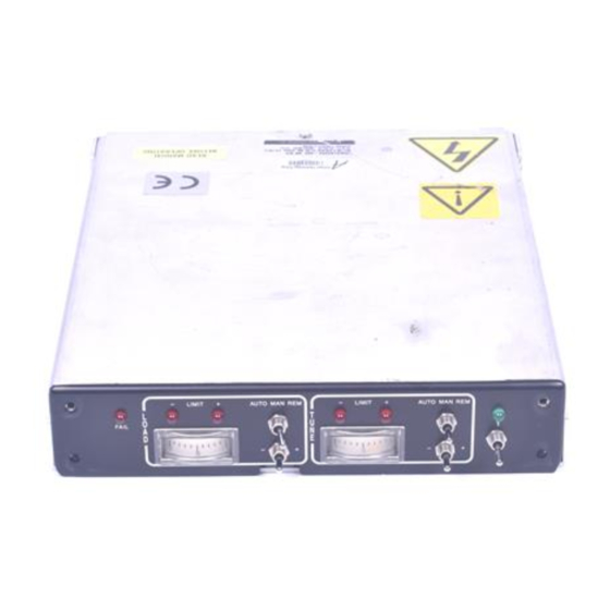
Advanced Energy FRONT PANEL SWITCHES AND INDICATORS Figure 4-6 identifies the switches and indicators on the front panel of the AMN PS-2A controller. Table 4-5 defines each of the numbered switches and indicators. Figure 4-6. AMN PS-2A Controller Front Panel Table 4-5. -
Page 36: Rear View Illustration
Power LED When lit, this LED indicates that power is being applied to the controller. REAR VIEW ILLUSTRATION Figure 4-7 shows the rear panel of the AMN PS-2A controller. magnitude error voltage ac input remote interface (J2) matching network... - Page 37 ® Advanced Energy 4-10 5708577-A...
-
Page 38: Chapter 5. Installation, Setup, And Operation
Chapter Installation, Setup, and Operation INSTALLING The following sections describe how to install the AMN PS-2A matching network controller. Unpacking Unpack and inspect your controller carefully. Check for obvious physical damage. If no damage is apparent, proceed with the unit connections. If you do see signs of shipping damage, contact Advanced Energy Industries, Inc., and the carrier... -
Page 39: Dimensional Drawing
® Advanced Energy DIMENSIONAL DRAWING Figure 5-1. Dimensions 5708577-A... -
Page 40: Mounting The Controller And Making Connections
AMN PS-2A Mounting the Controller and Making Connections Mount the AMN PS-2A controller in a convenient rack panel and connect the ac power cable. Note: When mounting the controller, ensure that the ac power connector is user accessible as it serves as the main power disconnect for the unit. -
Page 41: Electrical Verification
Figure 5-4. BNC-Type Connector (J3 and J4) Electrical Verification Once the AMN PS-2A controller is installed, use the following steps to verify that the unit is properly installed and connected: 1. Turn on the AMN PS-2A control using the ON/OFF switch on the front panel. -
Page 42: Automatic Mode
To operate the AMN PS-2A controller in automatic mode, place both the load and the tune AUTO/MAN/REM switches in AUTO position. - Page 43 ® Advanced Energy 5708577-A...
-
Page 44: Chapter 6. Troubleshooting And Global Support
Chapter Chapter Troubleshooting and Global Support Use the following sections to troubleshoot the AMN PS-2A or to find Global Support contact information. BEFORE CALLING AE GLOBAL SUPPORT Before calling AE Global Support, perform the following steps or procedures. RISK OF DEATH OR BODILY INJURY. Disconnect all sources of input power before working on this unit or anything connected to it. - Page 45 ® Advanced Energy 5. If the matching network is not tracking small variations in the system, the phase and/or magnitude gain may be set too low. To adjust, turn the phase and/or magnitude gain adjust potentiometers counterclockwise to increase the gain level. For an illustration of the gain adjustments on the rear panel, see “Phase/Magnitude Gain Adjustors”...
-
Page 46: Troubleshooting Flow Chart
AMN PS-2A Troubleshooting Flow Chart Use this chart to troubleshoot the AMN PS-2A controller. To begin, select the problem you are experiencing from the boxes on the left side of the diagram. PS-2A does not adjust Remote I/O servomotors cable properly Connect cable. -
Page 47: Ae Global Support
® Advanced Energy AE GLOBAL SUPPORT Please contact one of the following offices if you have questions. Table 6-1. Global Support Office Contact AE, World Headquarters Phone (24 hrs/day, 7 days/week): 800.446.9167 or 1625 Sharp Point Drive 970.221.0108 Fort Collins, CO 80525 USA Fax (M–F, 7:00 am –... -
Page 48: Returning Units For Repair
AMN PS-2A Office Contact AE, Taiwan, Ltd. Phone: 886-2-82215599 10F-6, No. 110, Chung Shan Rd. Fax: 886-2-82215050 Sec. 3, Chungho City, Taipei Hsien Taiwan 235 AE, China Phone: 86-755-3867986 Rm. 910 Anhui Building, Fax: 86-755-3867984 No. 6007 Shennan Road, Shenzhen, China 518040... -
Page 49: Authorized Returns
® Advanced Energy • Include the product serial number and a full description of the circumstances giving rise to the claim • Have been assigned a return material authorization number (see below) by AE Global Support All warranty work will be performed at an authorized AE service center (see list of contacts at the beginning of this chapter). - Page 50 AMN PS-2A Index Numerics error voltage input connectors (J3 and J4) connecting 115 Vac transformer wiring diagram 230 Vac transformer wiring diagram FAIL LED front panel indicators and switches adjustors, phase/magnitude gain authorized returns automatic mode gain magnitude gain adjustor...
- Page 51 ® Advanced Energy remote interface (J2) pollution degree J1, see matching network interface power J2, see remote interface input specifications 4-6, 5-4 J3 (phase error voltage input port) protection, over-current 4-6, 5-4 J4 (magnitude error voltage input port) rear panel illustration LEDs remote interface (J2) FAIL...
- Page 52 ® Advanced Energy temperature specifications theory of operation troubleshooting checks with the power off checks with the power on procedures tune LIMIT LEDs meter unpacking the controller use, conditions of user manual symbols used type conventions verification electrical warranty claims returning units for repair statement of weight of controller...
Need help?
Do you have a question about the AMN PS-2A and is the answer not in the manual?
Questions and answers