Table of Contents
Advertisement
Quick Links
California
Batteries, battery posts, terminals and related accessories contain
lead and lead compounds, and other chemicals known to the state
Proposition 65
of California to cause cancer and birth defects or other reproduc-
Warning:
tive harm. Wash hands after handling.
2600_Fahrenheit-2V-NB-mod_I&O.indd 1
2600_Fahrenheit-2V-NB-mod_I&O.indd 1
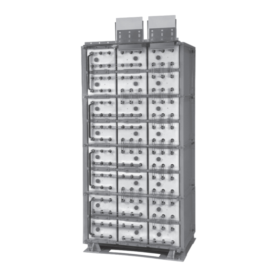
Fahrenheit 2V NB Module
Installation and Operation Manual
2/22/22 2:44 PM
2/22/22 2:44 PM
Advertisement
Table of Contents

Related Manuals for Deka Fahrenheit 2V NB


Summary of Contents for Deka Fahrenheit 2V NB
- Page 1 Fahrenheit 2V NB Module Installation and Operation Manual California Batteries, battery posts, terminals and related accessories contain lead and lead compounds, and other chemicals known to the state Proposition 65 of California to cause cancer and birth defects or other reproduc- Warning: tive harm.
-
Page 2: Table Of Contents
TABLE OF CONTENTS Safety Precautions System Operations Protective Equipment .........3 Charge Voltage ..........15 Procedures ............3 Charge Current ..........15 Temperature Compensation ......15 Receiving & Storage Cell Voltage ............15 Receiving Inspection ..........3 Rectifier Ripple Voltage ........15 Unpacking ............3 Record Keeping..........15 System Shipment ..........3 Storage / Refresh ..........4 Acceptance Testing ........16 Installation... -
Page 3: Safety Precautions
IN REFERENCE TO 7. Never remove or tamper with the pressure relief valves unless for cell replacement. Warranty void if vent valve is THIS MANUAL: removed. 8. Inspect all flooring and lifting equipment – “Cell” is defined as an individual 2-volt unit for functional adequacy. -
Page 4: Storage / Refresh
Cell Shipment RECEIVING & STORAGE CONT. Each cell will be in an individual sleeve. There will be a Module Shipment maximum of 6 cells per pallet. All battery accessories (connectors, terminal plates, hardware) will be included with a module pallet. The pallet will be indicated with an “Accessory”... -
Page 5: Installation General
Hardware Torque Requirements INSTALLATION Bolt Size Torque/Retorque General Caution should be taken when installing batteries to insure 1/2-13 100ft-lb 135.5 Nm no damage occurs. The battery cabinet, tray, rack, etc. shall be 3/8-16 45ft-lb 61.0 Nm inspected for sharp edges that could cause damage to the battery casing. - Page 6 SYSTEM INSTALLATIONS 7. Base and module layout should be compared to system CONT. layout diagram. All ½-13 x 1.75" hardware (2 per corner) 5. Remove hardware holding modules together (4 bolt assem- are to be installed on the inside of the module for module to blies) and holding modules to pallet (4 bolt assemblies).
- Page 7 8. Bolt assemblies (two per corner) are required on the 10. The system layout diagram should be consulted to outside of the module to complete the base to module determine module configuration. System design limits connection. All ½-13 x 1.75" hardware should be checked modules to be stacked no higher than 4 modules (8 cells for proper torque before proceeding.
-
Page 8: Cell Installation
SYSTEM INSTALLATIONS Star washers are to be installed with teeth towards module to CONT. ensure proper grounding. 11. Cell / Sleeve Installation — Install cells into modules. Cells Note: Top Plate hardware contains two different types of are shipped separate from modules. Cell polarity orientation star washers. -
Page 9: Electrical Connection
Bottom Shield Bracket Installation Bottom Retainer Bar 2. Module layout should be compared to system layout diagram and all hardware should be checked for proper Safety Shield Bracket Installation torque before proceeding. Consult “Hardware Torque Requirements” (pg 5) for proper torque values. 1. - Page 10 TERMINAL ASSEMBLY 5. Install terminal plate to battery posts using 1/4-20 x 1.00" CONT. hardware. 2. Remove module bolts directly behind location of terminal plate. 3. Replace flat washer with cap washer. Re-install 3/8-16 x Terminal Plate to be installed on battery posts as shown 1.25"...
-
Page 11: Side Termination
Side Termination 8. Lug Hole Layout — Top terminal plate designed to use up to 0.50" dia. bolt and a maximum 1.75" centers and Consult system layout diagram for side termination location. 1.188" min., 2 hole lug. 1. Remove safety shield bracket if required. .56 DIA. - Page 12 TERMINAL ASSEMBLY 7. Install Side Terminal Shield to Side Terminal Plate using CONT. ¼-20 screws. 4. Connect side terminal plate to side terminal plate connectors. Tighten but do not torque hardware. Side terminal bracket and side terminal connectors may have to be adjusted to insure plate and connectors are flush.
-
Page 13: Connector Assembly
CONNECTOR ASSEMBLY 5. NB battery systems are supplied with multiple connectors to be used per battery post. A 2CU connector package will 1. The contact surfaces of each individual post on every cell require 2 connectors per connection (1 per side), see ex- have been cleaned and coated with a thin film of No-Ox-ID ample below. -
Page 14: Safety Shield Assembly
CONNECTOR ASSEMBLY CONT. 4. Battery performance is based on the output at the battery terminals. Therefore, the shortest electrical connection between the battery system and the operating equipment results in maximum total system performance. Select cable size based on current carrying capability and voltage drop. -
Page 15: System Operations
Equalizing For top terminal assembly, align protective cover in front of top terminal plates. Mark area of protective shield that is required to Upon installation of the battery, an optional boost charge of be removed in order to fit between the terminals. Cut protective 2.40 vpc ±... -
Page 16: Acceptance Testing
RECORD KEEPING Upon completion of the acceptance test, the battery system CONT. should be placed on float charge at 2.25 volts per cell to restore the battery to its’ rated capacity. Batteries should not require an equalization charge once they have passed their initial acceptance test. Consult with East Penn Reserve Power’s Product Support group before performing additional equalizing charges on batteries that have successfully passed their initial acceptance test. -
Page 17: Capacity Testing
Capacity Testing 7 Thread Polypropylene rope through the battery posts as illustrated below and knot. Per IEEE 1188 “Capacity testing is used to trend battery aging. The result of a capacity test is a calculation of the capacity of the battery. The calculated capacity is also used to determine if the battery requires replacement.”... - Page 18 9. Pull cell from module onto lifting device. Care should be taken so lifting device does not come in contact with cell posts. 10. Replacement cell may have built up pressure while on open circuit. Refer to step 5 for relieving the internal cell pressure.
-
Page 19: Battery Maintenance Report
2600_Fahrenheit-2V-NB-mod_I&O.indd 19 2600_Fahrenheit-2V-NB-mod_I&O.indd 19 2/22/22 2:45 PM 2/22/22 2:45 PM... -
Page 20: Refresh Record Form
EPM ORDER NUMBER WILL APPEAR ON THE SHIPPING LABEL ON THE CARTON COVERING EACH PALLET OF CELLS TO ENSURE CONTINUATION OF WARRANTY, SUBMIT FORMS TO: East Penn Mfg. Co, Inc., Reserve Power Division, Product Support & Warranty Dept. (reservepowerwarranty@dekabatteries.com) Form available as an Excel spreadsheet. Consult your EPM or Deka Services Representative 2600_Fahrenheit-2V-NB-mod_I&O.indd 20 2600_Fahrenheit-2V-NB-mod_I&O.indd 20... -
Page 21: Base Anchor Hole Pattern
APPENDIX B BASE ANCHOR HOLE PATTERN Module Type 2 x 2 17.55 29.55 3 x 2 30.33 42.83 2600_Fahrenheit-2V-NB-mod_I&O.indd 21 2600_Fahrenheit-2V-NB-mod_I&O.indd 21 2/22/22 2:45 PM 2/22/22 2:45 PM... -
Page 22: Voltage Compensation Chart
APPENDIX C VOLTAGE COMPENSATION CHART Refresh/ °C Float °F Equalize >35 2.230 2.380 >95 2.232 2.382 93.2 2.234 2.384 91.4 2.236 2.386 89.6 2.238 2.388 87.8 2.240 2.390 86.0 2.242 2.392 84.2 2.244 2.394 82.4 2.246 2.396 80.6 2.248 2.398 78.8 2.250 2.400... - Page 23 2600_Fahrenheit-2V-NB-mod_I&O.indd 23 2600_Fahrenheit-2V-NB-mod_I&O.indd 23 2/22/22 2:45 PM 2/22/22 2:45 PM...
- Page 24 e-mail: reservepowersales@dekabatteries.com East Penn Manufacturing Co. Lyon Station, PA 19536-0147 Phone: 610-682-4231 Fax: 610-682-4781 www.dekabatteries.com All data subject to change without notice. No part of this document may be copied or reproduced, elec- E.P.M. Form No.2600 02/22 © 2022 by EPM Printed in U.S.A. tronically or mechanically, without written permission from the company.
Need help?
Do you have a question about the Fahrenheit 2V NB and is the answer not in the manual?
Questions and answers