Table of Contents
Advertisement
Quick Links
Before you Begin
The following is a complete list
of tank components:
• Tank top half
• Tank bottom half (with pre-installed
mid-seam gasket)
• Baffle (two-compartment configuration only)
• Seam clips (64)
• Support posts (2)
• Lids (2)
• Lid shipping screws (4) and washers (4)
• Lid spacers (1)
• Lid screw kits (2)
• Plumbing kit
The following tools facilitate
• Fork lift (5,000 lb [2,268 kg] capacity,
32" [0.81 m] load center, min. 66" [1.68 m]
arm, min. 12' [3.66 m] pick height)
• Infiltrator Lifting Strap Assembly*
• 22 oz. [0.6 L] spray bottle*
• 16 oz. [0.5 L] liquid soap*
• Utility knife
• Coarse-bristled paint brush
• Metal hammer (16-20 oz. [0.5 kg])
• Rubber mallet
• Hole saw (5" [125 mm] diameter)
• Nut driver (3/8", 5/16" sockets)
• Clean rags
• Headlamp or flashlight
• Screw gun
• Safety glasses
*Supplied in Infiltrator CM-1060 Starter Kit
WARNING
WARNING: These assembly instructions do not include a protocol for vacuum testing the CM-1060 tank. If required,
vacuum tests on the CM-1060 shall only be performed in strict accordance with Infiltrator's CM-1060 tank vacuum testing
guidance documents. Failure to follow an Infiltrator vacuum-testing protocol and/or exceeding 2.5 inches (63 mm) of
mercury vacuum pressure could result in personal harm. Never apply a positive air pressure to the CM-1060 tank. Infiltrator
will not be liable for any problems that arise from such unauthorized use.
Contact Infiltrator Water Technologies' Technical Services Department for assistance at 1-800-221-4436
Contact Infiltrator Water Technologies' Technical Services Department for assistance at 1-800-221-4436
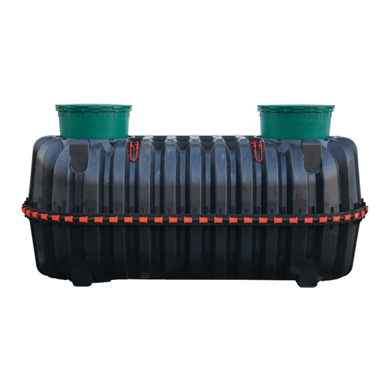
Infiltrator CM-1060 Tank
Assembly Instructions
Tank top and
bottom halves
Support Posts (2)
It is recommended that a minimum of two people participate to safely assemble the tank.
Assemblers must wear safety glasses during the entire assembly. The top half of the
tank weighs approximately 169 pounds (77 kg) and the bottom half of the tank weighs
approximately 162 pounds (74 kg) for a total approximate weight of 331 pounds (151 kg).
Each tank half must be lifted approximately 30 inches (750 mm) above ground during
the assembly process. There must be enough side and overhead clearance to freely
maneuver the tank components and to operate lifting machinery when used.
The CM-1060 tank must be assembled by an Infiltrator Water Technologies Authorized
Assembler. Tanks assembled by unauthorized assemblers will not be warrantied by
Infiltrator Water Technologies. A signed copy of the CM-1060 Tank Assembly Checklist &
Assembly Authorization is required for all Authorized Assemblers.
IMPLOSIONS MAY CAUSE SERIOUS INJURY
Follow Infiltrator Water Technologies, vacuum test instructions
NEVER EXCEED 2.5 inches mercury vacuum pressure
Seam Clips (64)
(2-compartment configuration only)
MARCH 2022
Lids (2)
Baffle
Advertisement
Table of Contents

Summary of Contents for Infiltrator CM-1060
- Page 1 Follow Infiltrator Water Technologies, vacuum test instructions NEVER EXCEED 2.5 inches mercury vacuum pressure WARNING: These assembly instructions do not include a protocol for vacuum testing the CM-1060 tank. If required, vacuum tests on the CM-1060 shall only be performed in strict accordance with Infiltrator’s CM-1060 tank vacuum testing guidance documents. Failure to follow an Infiltrator vacuum-testing protocol and/or exceeding 2.5 inches (63 mm) of mercury vacuum pressure could result in personal harm. Never apply a positive air pressure to the CM-1060 tank. Infiltrator...
- Page 2 WARNING: TThe Infiltrator Lifting Strap Assembly supplied with the starter kit is sized to pick up a maximum of four Infiltrator tank halves at one time. Never lift more than four tank halves at one time with the Infiltrator Lifting Strap Assembly.
- Page 3 • 35 – Minnesota, Indiana (15T) (35) Note: If you are assembling a 15E baffle, use the Infiltrator IM-1060 15E Baffle Assembly Instructions document. If you are assembling a 15T baffle, use the Infiltrator IM-1060 15T Baffle Assembly Instructions document. For all other baffle configurations, continue to Step 7.
- Page 4 45-degree angle relative to the seam rail. These seam clips must be attached along the seam rail from the outside in towards the tank centerline. Using a hammer and holding the top and bottom sides of the seam clip, tap the seam clip along the tank seam rail; the clip will pull toward the seam rail. Engage the clip to a full stop over the locking tabs; the seam clip will click into place when properly engaged. The seam clip is designed to lock in place with two or three swift blows of a hammer. If substantial resistance is encountered Contact Infiltrator Water Technologies’ Technical Services Department for assistance at 1-800-221-4436...
- Page 5 CAUTION! Do not use a metal hammer to strike the support posts as this may cause permanent damage. Note: If you are assembling a one-compartment tank configuration without a baffle, then proceed to Step 19. Otherwise, continue to Step 18. Contact Infiltrator Water Technologies’ Technical Services Department for assistance at 1-800-221-4436...
- Page 6 Note: Refer to Infiltrator IM- and CM-Series Septic Tank General Installation Instructions, Riser Connection Guidance, and Buoyancy Control Guidance documents, and state/local product approvals and applicable regulations prior to tank installation and use. 4 Business Park Road P.O.
Need help?
Do you have a question about the CM-1060 and is the answer not in the manual?
Questions and answers