Table of Contents
Advertisement
...Innovative liquid vaporizing and gas mixing solutions
Vertical electric single core vaporizer
Operations & Maintenance
Manual
151 South Michigan Street, Seattle, Washington, USA 98108
Tel: +1-206-789-5410
Fax: +1-206-789-5414
Web: www.algas-sdi.com
Briana
FILE: MANUAL PN 54629 TORREXX REV 11-2-21
2021.11.02
11:12:57
-07'00'
Advertisement
Table of Contents

Related Manuals for Algas SDI TORREXX TX240


Summary of Contents for Algas SDI TORREXX TX240
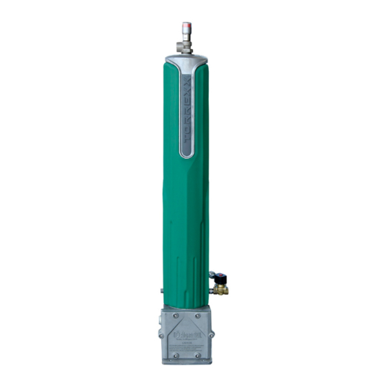
- Page 1 ...Innovative liquid vaporizing and gas mixing solutions Vertical electric single core vaporizer Operations & Maintenance Manual 151 South Michigan Street, Seattle, Washington, USA 98108 Tel: +1-206-789-5410 Fax: +1-206-789-5414 Web: www.algas-sdi.com Briana FILE: MANUAL PN 54629 TORREXX REV 11-2-21 2021.11.02 11:12:57 -07'00'...
- Page 2 WARNING Read the OPERATION MANUAL before operating this equipment. ■ NOTE: Algas-SDI reserves the right to use alternate manufacturers’ components as vendor delivery applicability dictates. Vendors have supplied literature contained in the Operation Manual. Please check to be sure supplied data matches your configuration.
- Page 3 WARRANTY REGISTRATION A Warranty Registration Card is located on the last page of this manual. Fill it out and send a copy either by mail to the address shown at the bottom of the form or submit via email to sales@algas-sdi.com. WARRANTY, COPYRIGHTS AND APPROVALS WARRANTY Algas-SDI International, LLC (ASDI) warrants that the equipment is free of...
- Page 4 SYMBOLS AND CONVENTIONS Special symbols are used to denote hazardous or important information. You should familiarize yourself with their meaning and take special notice of the indicated information. Please read the following explanations thoroughly. GENERAL WARNING OR CAUTION This symbol indicates hazards or unsafe practices, which can result in damage to the equipment or cause personal injury.
-
Page 5: Table Of Contents
TORREXX TABLE of CONTENTS 1. INTRODUCTION DESCRIPTION Figure 1 – TORREXX SSR Dimensional Drawing TORREXX VAPORIZER OPTIONS 2. MAJOR COMPONENTS DESCRIPTION Figure 2 – Heating System Figure 3 – Liquid Passage Prevention System MAJOR COMPONENTS LIST Figure 4 – TORREXX SSR Major Components Drawing 3. - Page 6 TORREXX TABLE of CONTENTS - Continued 4. OPERATION GENERAL 4-20 OPERATING INSTRUCTIONS 4-20 STARTING THE VAPORIZER 4-20 STOPPING THE VAPORIZER 4-21 PURGING THE VAPORIZER 4-21 5. MAINTENANCE GENERAL 5-22 INITIAL INSTALLATION AND OPERATION INSPECTIONS 5-22 ANNUAL MAINTENANCE REQUIREMENTS 5-23 Liqui-SAFE VALVE – PERFORMANCE CHECK 5-24 5-24 Figure 10 –...
- Page 7 TORREXX TABLE of CONTENTS - Continued SOLENOID VALVE ELECTRICAL TEST 6-39 6-39 Figure 16 – Solenoid Valve Electrical Test 7. TORREXX OPTIONS ECONOMY OPERATION 7-40 Figure 17 – TORREXX Economy Valve Installation 7-40 TORREXX ECONOMY VALVE MAINTENANCE 7-41 7-41 Figure 18A – STEP 1 – Unscrew the inlet housing from the outlet housing. 7-41 Figure 18B –...
-
Page 8: Introduction
INTRODUCTION DESCRIPTION The dimensional drawing (see page 1-2) identifies various components of the Algas-SDI TORREXX SSR model vaporizer. This equipment is intended for use with liquid propane, butane, or propane-butane mixtures. Multiple resistance heating elements provide thermal energy to the finned aluminum heat exchanger. A solid-state controller monitors the heat exchanger temperature and regulates the operating temperature to a predetermined set point. - Page 9 Figure 1 – TORREXX SSR Dimensional Drawing ASDI Operations and Maintenance – TX Models – P/N: 54629...
-
Page 10: Torrexx Vaporizer Options
TORREXX VAPORIZER OPTIONS Optional items for the TORREXX vaporizer are designed to enhance convenience for the end user and can be applied in the field to all models. This section provides a brief introduction to the options available for the TORREXX . - Page 11 4) Economy Valve – Allows use of propane storage tank natural vaporization when the storage tank can provide enough vaporization and pressure to satisfy the load requirements. 5) Remote Start/Stop Box – Includes remote start/stop capability and a status light indicating the vaporizer is ready for operation (solenoid valve open). IP65 (NEMA 4) enclosure.
- Page 12 SAFETY CAUTION Propane Odor can fade. CAUTION Vaporizer may be hot after or during use. CAUTION Allow only a TRAINED and FULLY QUALIFIED person to service this equipment. ASDI Operations and Maintenance – TX Models – P/N: 54629...
-
Page 13: Major Components
MAJOR COMPONENTS The TORREXX is designed to be reliable and user friendly. Several features allow you to quickly determine the status of your vaporizer. There are two basic control systems within a TORREXX Heating System – Figure 2 Liquid Passage Prevention System – Figure 3 Figure 2 –... - Page 14 Figure 3 – Liquid Passage Prevention System • RED FLAG INDICATES STATUS • VALVE IS TRIPPED WHEN FLAG IS UP (AS SHOWN) VALVE IS IN OPERATING POSITION WHEN FLAG IS DOWN (AS SHOWN) • FLOAT BALL ACTIVATED MANUAL RESET Liqui-SAFE VALVE DETECTS AND PREVENTS LIQUID FROM PASSING THROUGH...
- Page 15 Figure 4 – TORREXX SSR Major Components Drawing 1) Liquid Inlet Solenoid Valve 2) Valve, Gauge and Strainer kit components (Optional) 3) Transformer 4) Temperature Controller Board 5) Economy Valve (Optional) 6) Liqui-SAFE Valve with manual reset 7) Insulation Jacket 8) Solid-State Relays ASDI Operations and Maintenance –...
-
Page 16: Installation
INSTALLATION WARNING The equipment described in this manual is designed to operate with LP-gas, a flammable fuel under pressure. The nature of the application involves inherent hazards that could result in injury. Only a TRAINED and FULLY QUALIFIED person should service this equipment. -
Page 17: General
GENERAL Install the TORREXX vaporizer on a level firm base at least 6” (15 cm) above grade and secure it through the four ½” (13 mm) holes. Protect the equipment against damage from moving vehicles by use of an appropriate barrier. Consult state, provincial, insurance carriers, and local authorities for installation requirements. - Page 18 Figure 6 - Typical TORREXX Installation Drawing with Vapor Bypass & No Pump NOTES LIQUID PIPING LOSSES BETWEEN VAPORIZER AND THE TANK MUST NOT EXCEED HYDROSTATIC HEAD. TANK VAPOR INSTALL VAPORIZER 1 STAGE REGULATOR UPSTREAM OF PRESSURE VAPOR BYPASS LINE CONNECTION TO MAIN VAPOR LINE. REGULATOR* SET 1 STAGE VAPORIZER REULATOR 2-4 PSIG (0.1-0.3 BAR)
- Page 19 Figure 8 – Typical TORREXX Installation for Manifolding 2 Vaporizers. BALL VALVE WITH BALANCING ORIFICE Liqui-SAFE VALVE OVERSIZED COMMON HEADER VAPOR OUT NOTES: 1. USE 1” UNION AND BALL TORREXX VAPORIZER VALVE WITH BALANCING ORIFICES P/N 64004 ON ALL VAPORIZER OUTLETS 2.
-
Page 20: Liquid Line
LIQUID LINE Size the liquid line from the storage tank to the vaporizer to supply the vaporizer at full capacity with a minimal pressure drop. A liquid line- sizing chart is provided in Table 6. Install a liquid line strainer with magnet for iron particle pickup at the vaporizer inlet. -
Page 21: Safety Relief Valve
SAFETY RELIEF VALVE If the vaporizer is to be installed within an enclosure or building, vent the safety relief valve outside the enclosure and redirect the discharge upwards. A pipe-away adapter must be used at the relief valve. Always install a rain-cap or similar device to prevent water and other debris from entering the relief valve. -
Page 22: Wire Size
WIRE SIZE When selecting the type and size of wire used to install the TORREXX series electric vaporizers, please consider the following environmental information: ■ Maximum enclosure surface temperature: 65ºC (150 ºF). ■ Maximum enclosure ambient temperature: 80ºC (176 ºF). ■... - Page 23 Table 1 – Wire Length Chart [#4 AWG, 25 mm ] – Div. 1 only Table 2 – Wire Length Chart [#6 AWG, 16 mm ] – Div. 1 only ASDI Operations and Maintenance – TX Models – P/N: 54629 3-16...
- Page 24 Table 3 – Wire Length Chart [#8 AWG, 10 mm ] – Div. 1 and Zone 1 Table 4 – Wire Length Chart [10 AWG, 6 mm ] – Div. 1 only 3-17 ASDI Operations and Maintenance – TX Models – P/N: 54629...
- Page 25 Table 5 – Liquid Temperature vs. Tank Pressure Chart Propane Butane Liquid Tank Gauge Tank Gauge Temperature Pressure Pressure °F °C -43.73 -41.7 -39.6 0.10 -36.9 0.24 -34.1 0.39 -31.4 0.56 -28.6 10.7 0.74 -25.9 13.6 0.94 -23.1 16.7 1.15 NOTE: Below 30°F or -10°C, Butane is a liquid at normal...
- Page 26 Table 6 – LPG Liquid Line Sizing Chart (Minimum Pipe Size) Capacity of Distance from storage to vaporizer - feet (meters)* units MMBTU (Kcal) (GPH) (15) (23) (31) (36) (61) (92) (122) 1.146 ½” ½” ½” ½” ½” ¾” ¾” ¾”...
-
Page 27: Operation
OPERATION GENERAL TORREXX Electric Vaporizer utilizes a finned cast aluminum heater core. The heater core contains multiple cast-in resistance heating elements. Multiple wiring configurations allow a variety of AC input voltages to suit local power supply requirements. Liquid LPG enters the vaporizer through the liquid inlet solenoid valve at the base of the pressure vessel. -
Page 28: Stopping The Vaporizer
1) Close the outlet isolation valve. 2) Open all valves between the storage tank and the vaporizer to allow liquid flow to the vaporizer when the solenoid valve opens. 3) Apply power. If the upper control box lid is off, the solid-state relay LED lights should come on. -
Page 29: Maintenance
MAINTENANCE GENERAL TORREXX vaporizer is designed for long-term, trouble-free operation. Because of the nature of their use, and the severe duty they receive, it is important to perform scheduled maintenance. The maintenance schedule, type, and frequency provided in this manual is the minimum maintenance required for proper operation of the vaporizer. -
Page 30: Annual Maintenance Requirements
Annual Maintenance Requirements: Component Action Required Inlet strainer Remove plug and clean the screen. Replace screen if gaps or holes are present in the screen. If oils or contaminants are present, it may be necessary to use a cleaner to remove them. If magnetic plug is installed in the strainer, clean any debris off the plug using a lint-free rag. -
Page 31: Liqui-Safe Valve - Performance Check
Liqui-SAFE Valve – Performance Check Latch operation. – While the valve is in the open position and the red flag is down, press button and release QUICKLY. This will cause the valve to close and the red flag should pop up. Carefully press the button again all the way down and release SLOWLY. -
Page 32: Liqui-Safe Valve - Service Instructions
Liqui–SAFE Valve – Service Instructions There are four (4) o-rings in the Liqui-SAFE valve; the button post O-ring, valve body O-ring, valve seat O-ring and valve stem base O-ring. Follow the instructions below to service the Liqui-SAFE valve. Clean all the metal parts with WD-40. - Page 33 Figure 11C – STEP 3 – Replace button post internal O-ring. COMPRESS SUB-ASSEMBLY TO GAIN BEST ACESS TO THE O-RING. REMOVE USING FULL HOOK O-RING TOOL (SEE FIGURE 11D) REPLACE O-RING. APPLY WHITE LITHIUM GREASE PRIOR TO INSERTING BACK IN THE O-RING GROOVE. Figure 11D –...
- Page 34 Figure 11F – STEP 5 – Replace valve body static O-ring. USE O-RING HOOK TOOL TO REMOVE O-RING FROM O-RING GROOVE. SLIDE O-RING OVER STEM GUIDE. REPLACE O-RING. APPLY WHITE LITHIUM GREASE PRIOR TO INSERTING BACK IN THE O-RING GROOVE PULL VALVE STEM GUIDE UP Figure 11G –...
-
Page 35: Troubleshooting
TROUBLESHOOTING General Follow the troubleshooting guide below to identify the problem: NO FLOW OUT OF THE VAPORIZER IS Liqui-SAFE VALVE TRIPPED? SEE TROUBLESHOOTING TREE 2A SEE TROUBLESHOOTING TREE 1A ASDI Operations and Maintenance – TX Models – P/N: 54629 6-28... - Page 36 TREE # 1 A Liqui-SAFE VALVE TRIPS IS VAPORIZER WARM AND UP TO TEMPERATURE? PERFORM FULL LOAD CURRENT CHECK. SEE PAGE 6-36 SEE TROUBLESHOOTING TREE 1B IS CURRENT CHECK GOOD? PERFORM FULL LOAD VOLTAGE CHECK. REMOVE LIQUI-SAFE VALVE. SEE PAGE SEE PAGE 6-35 5-26 FOR SERVICE INSTRUCTIONS.
- Page 37 TREE # 1 B Liqui-SAFE VALVE TRIPS IS VAPORIZER POWER OFF? PERFORM SOLENOID VALVE LEAK TEST (SEE PAGE 6-39). SEE TROUBLESHOOTING TREE # 2A REPAIR OR REPLACE SOLENOID VALVE PERFORM LEAK TEST AGAIN TO ENSURE ISSUE IS CORRECTED. RESTART VAPORIZER ASDI Operations and Maintenance –...
- Page 38 TREE # 2A Liqui-SAFE VALVE DOES NOT TRIP NO LIGHT CHECK CONTROL BOARD LIGHT CHECK GREEN INCOMING POWER SEE TROUBLESHOOTING TREE #2C INCOMING POWER OK? SEE TROUBLESHOOTING TREE #2B CHECK CORRECT TRANSFORMER INCOMING WIRING POWER ISSUE BAD WIRING LOOSE CONNECTIONS. WIRING? REPLACE OR REPAIR ANY DAMAGED WIRING...
- Page 39 TREE # 2B Liqui-SAFE VALVE DOES NOT TRIP GREEN IS RELAY LATCHED? CHECK FUSE LINKS PRESS HI-LIMIT BUTTON TO RESET FUSE LINKS OPEN? VAPORIZER STARTS WORKING? REPLACE OPEN CHECK FOR LOOSE FUSE LINKS. WIRING CONTACT ASDI CHECK IF THERE IS 24V AT THE RELAY LEADING TO THE TEMPERATURE...
- Page 40 TREE # 2C Liqui-SAFE VALVE DOES NOT TRIP IS THERMOCOUPLE MOLEX PLUG OR TRANSITION HARNESS LOOSE DISCONNECTED? RECONNECT LOOSE OR DISCONNECTED MOLEX REINSTALL WIRES INTO TRANSITION HARNESS IS LED LIGHT RED PRESS RED RESET BUTTON TO ON CONTROL RESTART VAPORIZER BOARD? IF THE ABOVE ACTIONS DO NOT OPTIONAL...
-
Page 41: Full Load Voltage Check
Full Load Voltage Check NOTE Current flow depends on the applied voltage. Voltage lower than the specified voltage causes low current and may negatively affect operation. Make all measurements with the heater ON. WARNING These tests include high voltage. Exercise great caution in making the following tests. -
Page 42: Full Load Current Check
Full Load Current Check NOTE See fusible link detail below for typical fusible link installation. WARNING These tests include high voltage. Exercise great caution when performing the following tests. Carelessness could result in severe injury or death. L1 ALWAYS ENERGIZED. See additional warnings located at the beginning of this chapter. -
Page 43: Torrexx Electric Vaporizer Data Sheet
TORREXX Electric Vaporizer Data Sheet HEATER WIRE-TO-WIRE NOMINAL VOLTAGE CURRENT MODEL PHASE RESISTANCE RESISTANCE POWER (VAC) (OHMS) (OHMS) (kW) TX25 32.8 22.2 TX25 14.2 22.2 14.8 TX25 15.0 22.2 14.8 TX25 16.4 22.2 14.8 TX50 28.5 22.2 TX50 16.4 22.2 14.8 TX50 30.1... -
Page 44: Heater Core Resistance
Heater Core Resistance NOTE Refer to the data sheet for wire-to-wire resistance of your vaporizer. CAUTION Turn off electrical power at the disconnect before performing this procedure. Remove the lid on the upper control box. Measure the resistance across each pair of wires connected to OUTPUT (2) on the relays. -
Page 45: Solenoid Valve Leak Test
Solenoid Valve Leak Test 1) Shut the outlet isolation valve. The inlet isolation valve should be open. Start the vaporizer and allow it to heat up until the heaters shut off. This allows any accumulated liquid in the vaporizer to be forced back toward the supply tank. -
Page 46: Solenoid Valve Electrical Test
Solenoid Valve Electrical Test NOTE A multimeter is required for the following test. CAUTION Turn off electrical power at the disconnect before performing this procedure. Open the electrical housing at the vaporizer base. Disconnect the 2-PIN Molex plug connector and measure resistance between the pins. You should measure approximately 3 Ohms. -
Page 47: Torrexx Options
TORREXX OPTIONS Economy Operation The Economy Option minimizes the electric power required to meet your vapor demand by shutting off flow at the outlet of the vaporizer when the natural vaporization rate of the storage tank can supply enough vapor to meet the demand. -
Page 48: Torrexx Economy Valve Maintenance
TORREXX Economy Valve Maintenance The Economy Valve consists of a moving piston which opens and closes the valve’s outlet. The movement of the piston is driven by the pressure force balance between two different sized O-rings and a spring. Follow the instructions below to perform maintenance on the Economy Valve once every two years using the Economy Valve repair kit ASDI P/N 40869. -
Page 49: Agent Or Teflon Tape On These Threads
Figure 18C – STEP 3 – Clean all O-ring contact surfaces and the bottom surface of the outlet housing. Apply excess lithium O-ring grease to inside of both housings. Figure 18D – STEP 4 – Replace the three O-rings contained in the Economy Valve repair kit. Apply excess lithium O-ring grease to all O-rings. -
Page 50: Tx Remote Box
TX Remote Box Includes remote start/stop capability and a status light indicating the vaporizer is ready for operation (solenoid valve open). Connection between the box and the vaporizer is established trough the wire harness found on the inside the vaporizer explosion proof enclosure. Remote box is intended for indoor or outdoor installation in general purpose location. -
Page 51: Valve And Strainer Package
Valve and Strainer Package For TX25 and TX320 ASDI P/N 36923 ¾” NPT inlet, 1” NPT outlet FILTAIRE Contaminant Separator The FILTAIRE is a filtering device designed to trap heavy hydrocarbons commonly present in LPG vapor. It also traps other materials, which may be in the gas due to storage conditions and internal condition of the equipment. Impurities are collected in the system and periodically removed through the system blow down drain. -
Page 52: Appendix A - Technical Information
APPENDIX A TECHNICAL INFORMATION... - Page 53 TORREXX Vertical Electric Vaporizer Data Sheet CE / NEMKO LPG Vaporizer Refer to Nameplate on unit for the model and voltage information then look up specific information on the tables below. General Specifications: Applies to all units Electrical: 50 – 60 Hz, NEMA 4, 1 Phase units are 2 wire, 3 Phase units are 3 wire Starting Temperature: 55 ºC 131 ºF...
- Page 54 EU marking description CE Conformity Marking: CE (2460) Identification Number Notified 2460 Body involved in production control stage: Explosion Protection marking: Equipment Group: -/II Equipment Category: The equipment is intended for Zone 1 and Zone 2. The space inside the process vessel and process lines are considered as non-hazardous area therefore (-/II) in the marking code.
- Page 55 TORREXX Alternate Configuration Refer to Nameplate on unit for the model and voltage information then look up specific information on the tables below. Alternate configuration arises from use of alternate conduit assembly. Functionality is identical. General Specifications: Applies to all units Electrical: 50 –...
- Page 56 EU marking description CE Conformity Marking: CE (2460) Identification Number Notified 2460 Body involved in production control stage: Explosion Protection marking: Equipment Group: -/II Equipment Category: The equipment is intended for Zone 1 and Zone 2. The space inside the process vessel and process lines are considered as non-hazardous area therefore (-/II) in the marking code.
- Page 57 TORREXX VERTICAL ELECTRIC VAPORIZER DATA SHEET (CE / NEMKO CONFIGURATIONS) EQUIPMENT ELECTRICAL BUSSING MODEL PHASE VOLTAGE DRAWING DRAWING DIAGRAM TX240 5001 - 6003 5001-7010 0620 - 7010 TX240 5001 - 6003 5001-7010 0620 - 7010 TX240 5001 - 6003 5001-7010 0620 - 7010 TX320 5001 - 6003...
- Page 58 TORREXX Electric Vaporizer Spare Parts and Accessories (CE / NEMKO) REFERENCE SPARE PARTS TX240 TX240 TX320 TX320 380V 440V 380V 440V 400V 480V 400V 480V 415V 415V TEMPERATURE CONTROL BOARD KIT 40888 40888 40888 40888 TRANSFORMER 54575 54576 54575 54576 SOLID-STATE RELAY KIT 40969 40969...
- Page 80 ASCO Valve used by Algas-SDI...
- Page 81 SOLENOID NOISE Solenoid valves emit a sound when operated. When energized, they emit a clicking sound. Also, accompanying the operation of most AC valves, is AC hum. Whether or not AC hum is objectionable actually depends on the requirements and opinion of the user. Normal AC hum is the result of the constantly reversing magnetic field produced by alternating current.
- Page 86 Installation & Maintenance Instructions SERIES 8003G 8202G OPEN-FRAME, GENERAL PURPOSE, WATERTIGHT/EXPLOSIONPROOF SOLENOIDS Form No.V6584R8 INSTALLATION SERVICE NOTICE Check nameplate for correct catalog number, service, and wattage. Check front of solenoid for voltage and frequency. ASCOr solenoid valves with design change letter G" or H" in the catalog number (ex.
- Page 87 facilitate wiring, the solenoid may be rotated 360_. For the watertight and Cleaning explosionproof solenoid, electrical fittings must be approved for use in the All solenoid operators and valves should be cleaned periodically. The time approved hazardous locations. between cleaning will vary depending on medium and service conditions. In general, if the voltage to the solenoid is correct, sluggish valve operation, CAUTION: Cryogenic Applications - Solenoid lead wire excessive noise or leakage will indicate that cleaning is required.
- Page 88 Torque Chart Part Name Torque Value Inch-Pounds Torque Value Newton-Meters solenoid base sub-assembly & adapter 175 ± 25 19,8 ± 2,8 pipe adapter 90 maximum 10,2 maximum Remove red cap and push solenoid down. Then pry here to lift Remove red cap and red cap nameplate/retainer push solenoid down.
- Page 89 Torque Chart Part Name Torque Value in Inch-Pounds Torque Value in Newton-Meters terminal block screws 10 ± 2 1,1 ± 0,2 socket head screw 15 - 20 1,7 - 2,3 center screw 5 ± 1 0,6 ± 0,1 Open-Frame Solenoid Open-Frame Solenoid Indicates parts supplied Open-Frame Solenoid...
- Page 90 SCIENTIFIC 50 Hanover Road 1561 Columbia Highway 50 Hanover Road Printed in U.S.A. Form No. V6950R5 MMIl All Rights Reserved. Florham Park, New Jersey 07932 Aiken, South Carolina 29801 Florham Park, New Jersey 07932 Tel. (973) 966-2000 Tel. (803) 641-9200 Tel.
- Page 91 ASCOMATICA S.A. de C.V. ASCO Valve Canada ASCOTECH S.A. de C.V. Bosques de Duraznos No. 65-1003A P.O. Box 160 (Airport Road) Circuito Del Progreso No.27 Fraccionamiento Bosques de las Lomas Brantford, Ontario N3T 5M8 Parque Industrial Progreso MMIl All Rights Reserved. Form No.
- Page 92 Innovative Liquid Vaporizing and Gas Mixing Solutions WARRANTY REGISTRATION Type of Equipment: Serial Number: ASDI Sales Order #: Order Date: Purchased By: To help us give you better service, please fill out this warranty registration form and return it to ASDI to register your purchase and for follow up on the performance of ASDI equipment.
- Page 93 Algas-SDI International, LLC 151 South Michigan Street Seattle, Washington 98108 Ph.: 1.206.789.5410 Fax.: 1.206.789.5414 www.algas-sdi.com...
Need help?
Do you have a question about the TORREXX TX240 and is the answer not in the manual?
Questions and answers