Advertisement
Quick Links
Manufacturer:
Model Number(s):
Minimum Core Module Version:
UltraMatrix Firmware Revisions
Document Revision Date:
O
S
VERVIEW AND
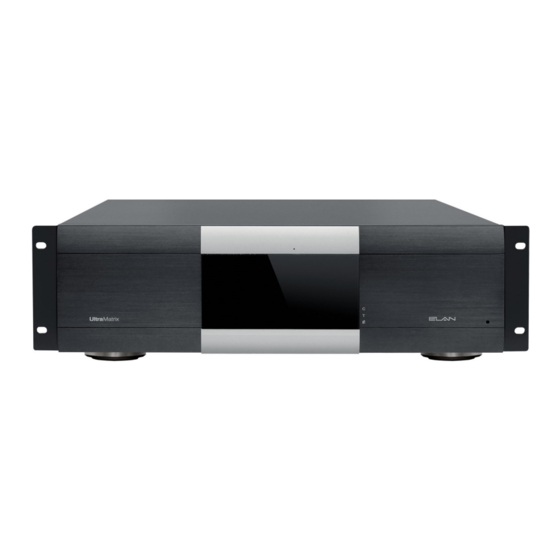
ELAN's UltraMatrix series of audio and video switchers provide matrix switching of HDMI, HDBaseT,
Analog Audio and Digital Audio signals and allows flexibility when creating centralized distribution music
and high performance video distribution systems. The UltraMatrix switchers were developed specifically
with integrated audio and video projects in mind. Audio centric features were included that provide
enhanced end user experience while input/output configurations that embrace the complexities of local
source inputs like video from a display with audio from architectural speakers, or using the video display
as a zone amplifier.
Elan switches connect to the g! system with a RS-232 serial connection or TCP/IP connection to allow
easy and reliable 2-way communication. Two Elan Matrix switchers can coexist in a network, but they
cannot be stacked.
T
HE FOLLOWING FEATURES ARE SUPPORTED
For a comprehensive list of supported features, please refer to the Elan UltraMatrix Designer's
T
HE FOLLOWING FEATURES ARE
For a comprehensive list of supported features, please refer to the Elan UltraMatrix Designer's
ELAN
gMV64
g! 7.1.609
gMV64: 1.13
05/01/2015
F
UPPORTED
EATURES
NOT
:
Guide
:
SUPPORTED
Guide
1 of 12
Integration Note
Advertisement

Summary of Contents for Elan UltraMatrix Series
- Page 1 Elan switches connect to the g! system with a RS-232 serial connection or TCP/IP connection to allow easy and reliable 2-way communication. Two Elan Matrix switchers can coexist in a network, but they cannot be stacked.
-
Page 2: Installation Overview
NSTALLATION VERVIEW 1. During the rough-in phase, install wires for the sources, amplifiers and displays for each zone. 2. Also during the rough-in phase, run a Cat5 wire from the location of the switch back to the Network Assembly of the g! system for RS-232 or Ethernet communications. Install the switch, the sources, amplifier, displays and speakers. - Page 3 ONNECTION IAGRAMS The ELAN UltraMatrix can be wired in various configurations and does not have a “standard” wiring diagram. Please refer to the ELAN UltraMatrix Designer’s Guide for a comprehensive list of wiring options and diagrams. 3 of 12...
- Page 4 g! C ONFIGURATION 1. Adding Driver a. Two drivers are available for the UltraMatrix switchers. i. Ethernet – control over TCP/IP – does not meet European power consumption regulations (ERP). The UltraMatrix device is discovered on the network and does not require a static IP.
-
Page 5: Hdmi Input
Add/Edit Source Dialog d. Open the dialog by pressing the “Edit” button e. From this dialog you configure all of the source parameters. Selections you make here ripple throughout the UltraMatrix setup so carefully make your selections. We recommend that you have a system diagram with you while programming. Display Name –... - Page 6 i. The all analog zone outputs and any analog/digital mirror output has a DSP (digital signal processing) circuit. One of the features of the circuit is to allow a source to be converted to Stereo, Mono, only Left or only Right, or Swap the L/R channels. Whatever you set here will be the output for all analog and analog/digital mirror zones.
- Page 7 d. Audio Output Type i. Define what type of audio connection this zone will have. HDMI, Coax digital and Analog are valid choices. 1. HDMI – used when the display or AVR is the sound source for the zone 2. Coax – used when connected to a digital amplifier or AVR 3.
- Page 8 g. Video Output i. Select the output that the display is connected to. HDMI and HDBaseT outputs are identical for this choice and we used the term “HDMI” just because it is more familiar than “HDBaseT”. 1. When displays are connected to both the HDMI and HDBaseT connections the EDID table uses the HDBaseT device for the video EDID and the HDMI device for the audio EDID h.
- Page 9 1. Digital delay may be applied to all sources routed through an analog or analog/digital mirror output. While calibrating use Save and Edit to test settings. m. Zone Features i. Group 1. A zone that is not subbed may be part of a zone group. Zone groups are very similar to Whole House Music zones.
- Page 10 iii. You will not see a performance difference from this action unless the UltraMatrix chassis has a power interruption. If you do not “Lock” then each time a display accesses a source for the first time after power restore it will take up to 30 seconds to negotiate a picture.
- Page 11 C ONFIGURATION ETAILS The following table provides settings used in the g! Configurator. Please refer to the g! Configurator Reference Guide and the ELAN UltraMatrix Designer’s Guide for more details. Devices Variable Name Setting Comments Communication Devices RS-232 Name <User Defined>...
-
Page 12: Common Mistakes
OMMON ISTAKES 1. No Paging Audio: On the gMV64, the analog paging source is must be used. On the 8x8 and 16x16, only the last Analog inputs can be used for the paging input. Either the left or right input can be used as the driver will sum the left and right channels to create MONO output.

Need help?
Do you have a question about the UltraMatrix Series and is the answer not in the manual?
Questions and answers