
Summary of Contents for Minster OBI Series
- Page 1 Manual No. 1010C MINSTER ® OBI/OBS SERIES PRESS MODEL Service Manual 8952-399 $15.00...
- Page 2 Manual No. 1010C MINSTER ® OBI/OBS SERIES PRESS MODEL Service Manual 8952-399 $15.00...
- Page 3 SERVICE IMPORTANT This manual has been prepared to furnish the press In order to more clearly show details of the Minster user with sufficient information to set up, lubricate, con- Model 101 OBI/OBS Series press, some covers, shields, nect air and electrical services, and stroke the press doors and guards have either been removed or left in the without outside assistance.
- Page 4 This manual has been especially prepared for those persons responsible for the SAFE operation and maintenance of Minster Model 101 OBI/OBS Series power presses. The technical information which it contains has been corre- lated, where possible, into related sections. Supporting illustrations and charts are also included to provide readers with quick reference to a given component or activity and to show the association of that component with related parts.
-
Page 5: Table Of Contents
Minster Standard Torque Value Chart ........ - Page 6 Minster Static Switch ........
- Page 7 CONTENTS Page SECTION F (Pages F-1 thru F-11) Servicing The Slide Assembly ............Gib Adjustment .
- Page 8 CONTENTS Page Periodic Cleaning ............... Spare Parts List .
-
Page 10: Section B
SECTION B This Section Contains The Following: Page Press Identification ..............B-2 Preparation For Use . -
Page 11: Press Identification
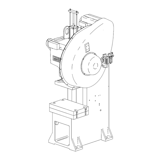
PRESS IDENTIFICATION Main Drive Motor (Optional) Counterbalance Assembly (N/A On Super Speed Press) Lifting Lug Flywheel Cover Limit Switch Air Line Lubricator Front Cover Clutch Solenoid Valve Slide Frame Bolster Plate B - 2... -
Page 12: Preparation For Use
OBSERVE ALL SAFETY PRECAUTIONS Check the point-of-operation safeguarding and make certain that it is appropriate for the operation being undertak- en. Refer to the “MINSTER Power Press Safety Manual No. 805” for additional safety related information. AND DON’T FORGET . . . -
Page 13: Press Safety
Additional safety suggestions are presented in the ation; secondly, the die should be fully guarded to pre- “Minster Power Press Safety Manual No. 805.” This vent them from doing so. Dies that cannot be fully manual was prepared as a guide for those persons who... -
Page 14: Section C
Minster Standard Torque Value Chart ........ -
Page 15: Press Installation
PRESS INSTALLATION SHIPPING AND RECEIVING Each Minster Model 101 OBI/OBS Series press is Lifting Lug carefully prepared for shipment to protect the press (One Each Side) during transit and to enable the customer to install the press with a minimum of reassembly when it arrives at its destination. -
Page 16: Assembly
THREADED FASTENERS SAE Grade 5 Standard threaded fasteners (bolts, screws, etc.) are used on Minster Model 101 OBI/OBS Series presses. When assembly torques greater than can be tolerated by Grade 5 hardware are required, Grade 8 fasteners are used. When a fastener is... -
Page 17: Press Foundation And Mounting
It is suggested by Minster that the user consult an experienced professional in the field of foundation layout when considering a suitable foundation for the press. -
Page 18: Front Panel And Lube Line Installation
DISCONNECT POWER TO THE PRESS, LOCK THE OBI presses and as also found within the DISCONNECT SWITCH IN THE OFF POSITION, AND “Minster Power Press Safety Manual No. ATTACH WARNING TAG TO PREVENT ACCIDEN- 805” in section entitled “Signs of Safety.”... -
Page 19: Electrical Connections
Connect the electrical supply leads to the drive motor according to the press wiring diagram and the 5. If a Minster Eddy Current Coupling is furnished, a interconnection diagram on the motor nameplate. separate service manual will be provided to fully Refer also to “Electrical Connections”... -
Page 20: To Calibrate The Digital Percent Of Load Meter
3. If the power supply and signal voltages are present, know the 100% or full load current rating of the drive but the meter does not function, return it to Minster motor. This amperage figure is shown on the motor for repair. -
Page 21: Digital Speed Meter Calibration
DIGITAL SPEED METER CALIBRATION NOTE: With the switch in the 0-200 position, the digit on the extreme right side of the display The switches and potentiometer used for calibration of is not used and will remain blank. In this the Digital Speed Meter are accessible through a cutout position, the reading is obtained from the in the rear cover plate of the unit. -
Page 22: Remote Controls
Minster upon request. from the left-hand side of the press. (See Figure 6C.) When returning a unit to Minster for repair, make certain it is carefully packaged to protect it from damage during shipment. Include, with the unit, a description of the problem(s) encountered and the serial number of the press on which it is used. -
Page 23: Inclining The Press
INCLINING THE PRESS 6. Insert both rear frame bolts through the aligned Minster Model 101 OBI Series presses are inclinable. holes in the press legs and frame. Install a 1.25” Flywheel presses may be inclined to one of four posi- Hex. -
Page 24: Auxiliary Equipment
NEVER FORCE THE INCLINING MECHANISM AFTER necessary, with an approved lubricant meeting the THE REAR FRAME BOLTS ARE INSTALLED. PRESS specifications of Minster Lubricant No. 1. (Refer to RIGIDITY IS OBTAINED BY TIGHTENING BOTH THE “General Lubrication Specifications For MINSTER FRONT AND REAR LEG BOLT NUTS. -
Page 26: Section D
Minster Static Switch ........ -
Page 27: Press Lubrication
Because of its completely automatic operation, period- reservoir with an approved lubricant meeting the spec- ic checks of the lube system are often either forgotten ifications of Minster Lubricant No. 1. (See “General or ignored. Such neglect could cause eventual bearing Lubrication Specifications For MINSTER Presses,”... -
Page 28: Initial Lubrication
Before operating the press for the first time, or if it is shot of Minster Lubricant No. 1 through the dot fit- installed in a new location, complete the following ting provided on the die cushion. - Page 29 Counterbalance Cylinder Slide Adjust Motor And Die-Namic Fixture Lubricator (Optional) Slide Ball Box Clutch Air Line Lubricator Figure 2D. Press initial lubrication. 10. Check the clutch air pressure indicated on the associated air pressure regulator at the rear of the press.
-
Page 30: Oil Cleanliness And Control
(See “Changing Oil In The Lube System.”) cle containing the contaminated oil with appropriate labeling and dispose of it in accordance with local Minster reserves the right to void all equipment government waste disposal regulations. warranties unless only approved lubricants are used in our presses and auxiliary equipment. -
Page 31: Lube System Oil Filter
Socket Head 5. Pour an approved lubricant meeting the specifica- Plugs (A) tions of Minster Lubricant No. 1 into the new filter to Cylinder End a level which is approximately 1.00” (25.4 mm) from Main Line From Pump Plugs (B) the top of the filter. -
Page 32: Flow Switch
Minster Static Switch CAUTION Whenever the lube system flow switch is used to con- trol inductive loads or high current circuits, the Minster Bul. 491-0011 static switch is furnished. This is a solid MAINTENANCE PERSONNEL SHOULD ALWAYS state A.C. switching unit which is completely encapsu- MAKE CERTAIN THAT POWER IS DISCONNECTED lated and sealed. -
Page 33: To Check The Static Switch
The flow switch is connected between terminals “G” and “A1”. Closing the flow switch contacts will cause 110 V.A.C. to be applied to the load from terminal “A2”. The other lead from the load should be connected to the press electrical common (press ground connection). To Check The Static Switch: If the flow switch is closing normally, but press clutch cannot be engaged and lube fault light is illuminated,... -
Page 34: Summary Of Lubrication Areas
Minster Lubricant No. 3. (Refer to “General Lubrication Specifica- 7. Air Line Lubricator(s) tions For MINSTER Presses,” Manual No. 507, for a list of approved lubricants and recommended suppliers.) A Minster die cushion is lubricated via a one shot lubricator. The lubricator handle should be pulled once every four (4) hours of operation. -
Page 35: Lubrication Areas
LUBRICATION AREAS (Refer to “Summary of Lubrication Areas” on page D-9 for lubrication instructions.) D - 10... -
Page 36: Section E
SECTION E This Section Contains The Following: Page Press Servicing ............... . E-2 Safety Precautions . -
Page 37: Press Servicing
For further information on lockout procedures, refer to system in order to complete some of the press inspec- the section entitled “Lockout Procedures for Mechani- tion checks. cal Power Presses” in the “Minster Power Press Safety Manual,” Manual No. 805 (furnished). WARNING WARNING... -
Page 38: Servicing The Pneumatic System
80 to 125 psi (5.5 to 8.6 Bar). air components installed by Minster and may include (See section entitled “Air Supply Connections,” page optional items needed for the operation and control of C-9.) In addition to proper air supply pressure, it is the... -
Page 39: Air Filter
pressure to the die cushion (if provided) is dependent WARNING upon customer requirements. To adjust the air pres- sure, turn the regulator handle until the desired pres- sure is indicated on the associated air pressure gauge. AFTER OPERATING AND LOCKING THE AIR Turn the regulator handle clockwise to increase, coun- LOCKOUT VALVE, OPEN ALL BLOWDOWN terclockwise to decrease, air pressure. -
Page 40: Air Pressure Switches
Then fill the lubricator to the line on the bowl with an switch with a new unit. approved lubricant meeting the specifications of Minster Lubricant No. 3. (Refer to “General Lubri- cation Specifications For MINSTER Presses,” Man- ual No. 507, for recommended lubricants and suppliers.) Do not over fill. -
Page 41: To Adjust The Clutch/Brake Air Line Lubricator
6. Replace the fill plug and tighten securely. WARNING 7. Open the air lockout valve to restore air pressure to the press. IMPORTANT: NEVER allow the lubricator to run NEVER ATTEMPT TO ADJUST THE AIR LINE dry. Check oil level in the lubricator LUBRICATOR WHILE THE FLYWHEEL IS ROTAT- ING OR THE DRIVE MOTOR IS TURNED ON. -
Page 42: Counterbalance System
COUNTERBALANCE SYSTEM • Aids press drive to overcome slide dynamics • Theory of Operation Aids shutheight adjust mechanism to raise or Counterbalances on mechanical power presses are lower the slide used to offset or counterbalance the weight of the press IMPORTANT: slide and upper die. -
Page 43: Air Pressure Adjustments
The NOTE: Excessive counterbalance pressure will force Minster data plate has a box marked as effective area the slide upward and conversely, low pressure (EFF. AREA XX SQ IN.) This effective area is the total... -
Page 44: Effects Of Improper Pressure
Effects of Improper Pressure With air pressure turned off, check tightness of coun- terbalance mounting bolts, rods and brackets. Perform Having insufficient counterbalance air pressure can this check at least once per month. At the same time lead to the following: check alignment of the cylinder with slide. -
Page 45: Flywheel Brake
5. Discharge all air pressure from counterbalance 17. Clean the mating surfaces of the air cylinder head surge tanks and cylinders at the air regulator or and the air cylinder to remove any RTV Sealant the remote drain cock. To be certain all pressure is adhering to the mating surfaces. -
Page 46: Flywheel Brake Maintenance
WARNING WARNING NEVER ATTEMPT TO INSTALL OR ADJUST DIES IN NEVER PRESSURIZE THE FLYWHEEL BRAKE THE PRESS, OR REMOVE DIES, WHILE THE FLY- WHILE IT IS REMOVED FROM THE PRESS FOR WHEEL IS TURNING. KINETIC ENERGY REMAIN- REPAIR OR OTHER MAINTENANCE. PRESSURIZ- ING WITHIN A TURNING FLYWHEEL COULD ING THE BRAKE UNDER THIS CONDITION COULD STROKE THE SLIDE, IF THE CLUTCH WERE ACCI-... -
Page 47: To Check For Air Leaks In The Die Cushion System
NOTE: Two (2) types of die cushions are provided NEVER ATTEMPT TO DISMANTLE ANY PART OF by Minster, a rail mounted die cushion and THE DIE CUSHION ASSEMBLY UNTIL ALL PRES- a trunion mounted die cushion. Refer to the... -
Page 48: To Replace Trunion Mounted Die Cushion System Air Seals
- 8 x 2.50” long Socket Head Cap Screws that (Ref. Figure 10E) secure the bottom plate to the lower cylinder. Two NOTE: The following procedure applies to Minster die (2) of the mounting bolt holes are tapped (1.25” - cushions only. Refer to service information sup- 7) for handling purposes. - Page 49 Cylinder Piston Cover Plate Trunion Pin Trunion Pin Air Tank Piston Seal Lower Cylinder Gasket Bottom Plate Figure 10E. Trunion mounted die cushion. 8. Remove the four (4) clamping collars from the 13. Place a new gasket on the lower cylinder, then trunion pins.
-
Page 50: Air Reservoir Tanks
AIR RESERVOIR TANKS FUSIBLE PLUGS (Ref. Figure 11E) (Ref. Figure 11E) Reservoir tanks store a reserve of air and help to A fusible plug is installed in each reservoir tank to pro- assure proper operation of a component by minimizing tect personnel and equipment by releasing air pressure the pressure drop that occurs when a component is before it reaches a point of danger. - Page 52 SECTION F This Section Contains The Following: Page Servicing The Slide Assembly ............Gib Adjustment .
-
Page 53: Servicing The Slide Assembly
SERVICING THE SLIDE ASSEMBLY The inspection and servicing procedures described in this section should only be performed by authorized personnel who are experienced in the maintenance of Slide mechanical power presses. Normally, the adjustments outlined need be performed only if related parts of the press have been disassembled or an inspection reveals the need for readjustment. -
Page 54: To Adjust Gib Clearance
parallelism affects die alignment and quality of the work WARNING produced. Angularity is correct if the slide can be moved from top to bottom of stroke without moving toward front or rear of the press or to either side. Maximum angular- MAKE CERTAIN THAT POWER IS DISCONNECTED ity of Model 101 OBI/OBS Series presses is .0004”... -
Page 55: To Check Slide Vertical Angularity
9. Exhaust air from slide counterbalance cylinder (if 4. Place the POWER, OFF-ON-BAR Selector Switch provided). in the ON position. 10. Clean the slide face and the top surface of the bed 5. Start the main drive motor. Make certain that oil is (or bolster). -
Page 56: Calibration Of The Shutheight Indicator
10. Attach magnetic base dial indicator to the bottom EXAMPLE: If the above measurement is being of the slide. Position the dial indicator so that its performed on a press with a 6.00” spindle contact point is perpendicular to, and rest- stroke, the last third of the downward ing against, the flat inner surface of the square. -
Page 57: To Check Calibration Of The Shutheight Indicator
6. Turn ON the air supply to the press. Charge the .250” - 20 x .375” Long Set Screw counterbalance cylinder (if applicable) with air pres- sure that is greater than the amount shown for “0” die weight. If the press is not equipped with a coun- Shutheight terbalance cylinder, place a hydraulic jack between Indicator... -
Page 58: Slide Ball Box
connection caps are reassembled. A chart of recom- Attach a WARNING sign to the press controls to mended torque values for the cap screws used to warn other personnel that the press is currently secure the main and slide connection bearing caps is being serviced. -
Page 59: To Adjust Slide Ball Box Clearance
To Adjust Slide Ball Box Clearance: screw, loosen the set screw and back off the adjust- ing nut a small amount. Retighten the set screw and NOTE: Instructions are provided for adjustment of then recheck the force required to turn the connec- both the manual type slide adjustment and tion screw. -
Page 60: To Adjust Crossbar Knockout
CAM KNOCKOUT A cam knockout arrangement is also available as an option. This mechanism, however, requires a special Clamp slide and is available only when ordered on a new Screw press or by replacing the complete slide assembly. A cam knockout requires adjustment when the slide shut- height is changed. -
Page 61: Slide Installation
5. As the slide approaches the bottom of the stroke, Set Initial Clearance at make certain that the cam follower remains in con- .875” (22.2 mm) tact with the cam. If the cam follower will not remain Gib Adjusting Bolts in contact with the cam, stop the main drive motor. -
Page 62: Factor Affecting Parallelism And Vertical Movement
13. While an assistant maintains pressure on the slide, check clearance between the slide and the .03” .03” untightened gib. Total gib clearance should not exceed 0.003” to 0.004” (0.076 to 0.101 mm). 14. If gib clearance is satisfactory, relieve pressure on the slide and tighten gib mounting bolts and lock adjusting screws. - Page 64 SECTION G This Section Contains The Following: Page Servicing The Frame And Drive Assembly ..........G-2 Relieving A Slide From A “Stuck On Bottom”...
-
Page 65: Servicing The Frame And Drive Assembly
SERVICING THE FRAME AND DRIVE ASSEMBLY This section contains instructions for relieving a slide 6. Start the main drive motor and place the Stroking from a “stuck on bottom” condition, checking bearing Selector Switch in the INCH position. Then inter- clearances, and installing replacement bushings. -
Page 66: Total Bearing Clearance
5. Determine slide position (i.e., before or after bottom 6. Place the Stroking Selector Switch in the INCH of stroke). This will determine the direction the fly- position. Then position the slide at Bottom Dead wheel should be rotated. Center (BDC) of the stroke. 6. -
Page 67: Individual Bearing Clearances
TO CHECK INDIVIDUAL TOTAL BEARING CLEARANCE CHART BEARING CLEARANCES: PRESS SIZE TOTAL CLEARANCE EQUIPMENT REQUIRED: .0065” to .011” • Base Mounted Dial Indicator (calibrated 0.001” or No. 4 - 101 (.165 mm to .279 mm) 0.01 mm) • Hydraulic Jack .008”... - Page 68 7. Stop the main drive motor and place the Stroking 10. Place a dial indicator on the press frame and indi- Selector Switch in the OFF position. Make certain cate to the crankshaft. Make certain the indicator that the flywheel has stopped turning completely. is placed on the flywheel (or main gear) side of the Attach a WARNING sign to the press controls to press.
-
Page 69: Main Bearings And Connection Bearings
This check should be made to deter- Main Bushings — Replacement main bushings, avail- mine if any excessive wear has taken place. able from Minster, are normally supplied with bores machined to provide proper running clearance. Further BUSHING FITTING PRACTICE honing, scraping, or fitting is seldom required;... - Page 70 SECTION H This Section Contains The Following: Page Press Application ............... H-2 Tonnage .
-
Page 71: Press Application
H-3. press closely matching requirements of the die can be selected. MINSTER presses are built in a wide It can be established then, that in a mechanical press, range of tonnages, widths, drives, stroke lengths and the drive is designed to deliver full rated tonnage only speeds. -
Page 72: Tonnage/Stroke Relationship
out by setting the slide down “a little more” because positioned near the midstroke where the mechanical coining loads may be developed which reach danger- advantage is about 1 to 1 (or no mechanical advantage ous proportions; frame parts could be damaged. at all). -
Page 73: Press Drives
Tonnage Charts, pages H-5 thru H-7. Six different tonnage charts are included in the manual — for the #4 thru #7 Minster O.B.I. flywheel type press and the #6 & #7 Minster O.B.I single geared presses. PRESS DRIVES... - Page 74 OBI #4 Flywheel Distance off Bottom vs. Tonnage Available 2” Stroke 3” Stroke 4” Stroke 0.00 0.25 0.50 0.75 1.00 1.25 1.50 1.75 2.00 Distance off Bottom (inches) OBI #5 Flywheel Distance off Bottom vs. Tonnage Available 3” Stroke 4” Stroke 5”...
- Page 75 OBI #6 Flywheel Distance off Bottom vs. Tonnage Available 3” Stroke 4” Stroke 5” Stroke • 6” Stroke 7” Stroke 0.00 0.25 0.50 0.75 1.00 1.25 1.50 1.75 2.00 2.25 2.50 2.75 3.00 Distance off Bottom (inches) OBI #7 Flywheel Distance off Bottom vs.
- Page 76 OBI #6 Geared Distance off Bottom vs. Tonnage Available 4” Stroke 5” Stroke 6” Stroke • 7” Stroke 0.00 0.50 1.00 1.50 2.00 2.50 3.00 3.50 Distance off Bottom (inches) OBI #7 Geared Distance off Bottom vs. Tonnage Available 4” Stroke 5”...
-
Page 77: Punch Speeds
PUNCH SPEEDS It should be pointed out that not all of the energy stored in the flywheel can be used in normal press operation. Velocity of the slide at the time the die strikes the work- Actually, just a portion of the stored energy is used to piece has a very definite affect upon quality of the part, do the work of forcing the slide and its associated dies scrap loss, die life and economics of the operation. - Page 78 SECTION I This Section Contains The Following: Page Inspection & Maintenance ............. . . Periodic Cleaning .
-
Page 79: Inspection & Maintenance
It should user management. Such a program is vital to the safe- include checkpoints recommended by Minster, plus ty of press operators and necessary for continuous, others that are special or applicable to the particular efficient production from the equipment. -
Page 80: Spare Parts List
Many minor difficul- List” is required, please send your request to the atten- ties grow into major maintenance problems because of tion of the Minster Repair Parts Department. Be sure to neglect. specify the serial number of the press. Spare or... -
Page 81: Press Inspection Check List & Maintenance Record
MINSTER Press Inspection Check List & ® MODEL 101 OBI/OBS Series Press Maintenance Record Auxiliary Equipment Press Serial No. Press Model Feed Scrap Shear User’s Equip. No. Reel Cradle Location Straightener Stock Oiler Tonnage Other Installation Date Type Of Point Of Operation Guarding... -
Page 82: Mechanical Press Parts
Mechanical Press Parts (Continued) Monthly Checks ! Make certain no foreign material is lodged between bolster and bed. Bolster Plate ! Make certain bolster is mounted securely to bed. ! Check clutch brake anchor pins for tightness. ! Check clutch for loose or broken parts. ! Check clutch for air leakage. - Page 83 Mechanical Press Parts (Continued) Semi-Annual Checks ! Check total bearing clearance. (NOTE: Checking procedures and clearances are given in the manual.) ! Check R.H. main bearing clearance. Bearing ! Check L.H. main bearing clearance. Clearance ! Check connection bearing clearance. ! Check ball box clearance.
-
Page 84: Pneumatic Components
! Check for air leakage. (Procedure explained in manual.) C’Bal. ! Check oil level in lube cup. Resupply, if necessary, with Minster Lubricant No. 1. Cylinder ! Check for tightness of mounting bolts and alignment with slide. ! Check for air leakage. (Procedure explained in manual.) Die Cushion ! Check to make certain cylinder is being lubricated properly. - Page 85 COMMENTS: CORRECTIVE STEPS TAKEN: Press approved for operation. Inspected By Press NOT approved for operation. I - 8...
-
Page 86: Weekly Checks
NOT over lubricate. NOTE: The following procedures are applicable if the limit switch supplied is furnished by Minster. If controls are supplied by someone other than Minster, refer to the infor- mation furnished with that equipment. ! Check drive to limit switch for loose, worn, or damaged parts. Check the condition and Limit Switch tightness of protective cover. - Page 87 COMMENTS: CORRECTIVE STEPS TAKEN: Press approved for operation. Inspected By Press NOT approved for operation. I - 10...
-
Page 88: Weekly Checks
NOTE: Filter must be replaced with new filter of the same type each time the oil in Oil Filter the reservoir is replaced. ! Once a year, apply one shot of Minster Lubricant No. 2 through the fitting provided on Inclining Jack the jack gear box. - Page 89 COMMENTS: CORRECTIVE STEPS TAKEN: Press approved for operation. Inspected By Press NOT approved for operation. I - 12...
- Page 90 ADDITIONAL COMMENTS: I - 13...
- Page 91 MINSTER ® The Minster Machine Company, Minster, Ohio 45865 Phone: (419) 628-2331 / Fax: 419-628-3517 Distributors strategically located throughout the world. MMC0208...
- Page 92 MINSTER ® The Minster Machine Company, Minster, Ohio 45865 Phone: (419) 628-2331 / Fax: 419-628-3517 Distributors strategically located throughout the world. MMC0208...
Need help?
Do you have a question about the OBI Series and is the answer not in the manual?
Questions and answers