Table of Contents
Advertisement
Quick Links
Advertisement
Table of Contents

Summary of Contents for Eastey EC Series
- Page 1 EC1248, EC1848 & EC2472 Eastey EC Series Variable Speed Conveyors User Guide...
- Page 3 EC1248, EC1848 & EC2472 Eastey EC Series Variable Speed Conveyors User Guide Revised 01/11/2022 P/N C001000 Rev C1 Copyright and Trademarks Copyright ©2017-2022 Engage Technologies Corporation All rights reserved. All trademarks and brand names are the property of their respective owners.
-
Page 5: Table Of Contents
Contents: Safety ..........................7 Explanation of Symbols ....................8 Introduction ........................9 Eastey EC Series Variable Speed Conveyor Overview ..........9 Specifications ......................10 Dimensions ......................... 12 Installation ........................13 Optional Casters ......................13 Move Conveyor into Operating Location ..............13 Height Adjustment and Leveling ................. -
Page 7: Safety
Safety 7 Safety General Safety Precautions Before installing, operating or servicing this equipment, please read the following precautions carefully: • This machine is equipped with moving belts. Do not place hands near the rear of this unit when the belts are moving as fingers may be pinched where belts enter the frame. -
Page 8: Explanation Of Symbols
8 Safety Explanation of Symbols Caution sign or Safety Alert symbol. Indicates caution, be alert, Your safety is involved. Knowledge of safe operation is required. Ground symbol. Indicates ground. Use Class-3 (lower than 1000) cable to ground to earth. Incomplete grounding may lead to electrical shock. Electrical hazard. -
Page 9: Introduction
Introduction 9 Introduction Eastey EC Series Variable Speed Conveyor Overview Movable Mounting Plate Is Magnetically Pre-Drilled for Attached Control Easy Attachment Side Plates Box Can Be of Supports for Pre-Drilled for Repositioned As Standard Items Easy Desired Along Such as Print... -
Page 10: Specifications
Explanation of Model Numbers • E = Manufactured by Eastey Enterprises Inc., division of Engage Technologies. • C = Conveyor. EC Series variable speed conveyor offer a reliable stand-alone product transport for primary or secondary product marking, and make a convenient add-on infeed or exit conveyor to existing case taping or shrink wrapping equipment. - Page 11 • Optional guide rails available • Safety cover over pinch points • Adjustable conveyor height • Smooth, consistent belt speed Eastey Conveyor Optional Accessories Additional Print Head Mounting Plate Predrilled to mount full family of Squid Ink Printing Systems. Guide Rails...
-
Page 12: Dimensions
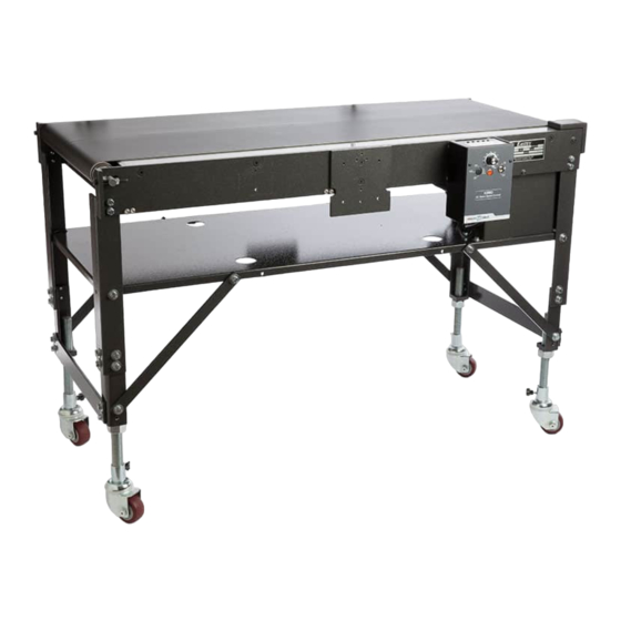
12 Introduction With Leveling Feet (Standard) With Optional Locking Casters Dimensions... -
Page 13: Installation
Move Conveyor into Operating Location Move the Eastey EC Series Variable Speed Conveyor to the desired location where it will be operating. If the conveyor is equipped with the standard leveling feet, it may require some lifting, but will easily skid across a smooth level floor surface. - Page 14 14 Installation Raising the Conveyor Begin raising the conveyor by turning the feet clockwise, as viewed from above. Raise Raise Note: Thread-locking compound is used to secure the feet or optional casters to the leveling leg. If you will be raising the conveyor more than inches from the minimum shipping height, thread the threaded-rod leg all of the way out of the bottom of the conveyor leg- extension angle bracket and thread a 1”-8 UNC standard nut (4 provided –...
- Page 15 Installation 15 Leg Extension Angle Brackets For fine-adjustment of the leg height, twist to thread the threaded-rod leg into or out of the conveyor leg angle bracket to adjust each leg up or down. (Loosen the 1”-8 UNC standard nut when applicable to allow adjustment of the threaded rod.) If the conveyor is to be raised more than 5- inches in height from minimum shipping height, extend the leg extension angle brackets on all four corners.
-
Page 16: Location Requirements
An open-end wrench or channel-style wrench with a 1-½” opening is required for the 1”-8 UNC standard nuts. Location Requirements When installing the Eastey EC Series Variable Speed Conveyor please be aware of the following considerations: 1. The mounting surface is flat and level. -
Page 17: Mounting The Ink Jet Printer
Installation 17 Mounting the Ink Jet Printer There are mounting holes predrilled that allow you to mount a variety of printing systems on the Variable-Speed Conveyor. Refer to the User Guide that came with your printer for mounting instructions. The illustrations that follow in this section show examples of possible locations for attaching mounting brackets for some common printer configurations. -
Page 18: Guide Rail Assembly And Installation (C0000501 Or C0000511)
18 Installation Example of Variable Speed Conveyor with Squid Ink PZ Mounting Bracket or DOD Mounting Bracket For a Squid Ink PZ or DOD printer, fasten the applicable mounting bracket to the Variable Speed Conveyor side plate as shown in the illustration below. Refer to the User Guide that came with your printer for mounting instructions. -
Page 19: Operation
Operation 19 Operation Power With the toggle Power Switch set to the Off position and Speed Control Dial set to minimum setting (0) Plug the power supply cord into a properly wired and grounded outlet. Speed Control Dial Power Allow Motor On / Off to Stop... -
Page 20: Control Box
20 Operation Control Box The conveyor control box is held in place by magnets and is repositionable. It can be repositioned anywhere along the metal surface of the conveyor frame side rail where it will be most convenient for operation. Speed Control Dial... -
Page 21: Adjustments
Adjustments 21 Adjustments Shut off power and disconnect electrical connections before making any adjustments. Height Adjustment and Leveling All four legs at the corners of the conveyor are adjustable for height and leveling, and two mechanisms allow for height adjustment: threaded-rod legs and leg-extension angle brackets. - Page 22 22 Adjustments Note: Thread-locking compound is used to secure the feet or optional casters to the leveling leg. Leg Extension Angle Brackets Leg-extension angle brackets in each of the four legs of the conveyor frame provide five inches (5”) additional height when extended, or less five inches (5”) when retracted. When extending or retracting the leg-extension angles, it is recommended to reposition the leg brace strap accordingly for stability.
-
Page 23: Conveyor Tension Adjustment
Adjustments 23 Conveyor Tension Adjustment Adjustment of conveyor tension is made by tightening or loosening the conveyor tension adjustment screws. There is a tension adjustment screw on each side of the conveyor at the right and left ends of the idler shaft. Jam nuts secure the tension adjustment. Tension Adjustment Tension... -
Page 24: Advanced Speed And Control Function Adjustment
24 Adjustments Advanced Speed and Control Function Adjustment The following illustration shows the D.C. board housed in the conveyor Control Box. Adjustments explained in this section refer to adjustments made by turning potentiometers on this board. Basic KBMM™ Controller Board Connection Diagram KBMM™... - Page 25 Adjustments 25 Note: In order for the IR comp and CL trimpot settings to be correct, the proper Plug-In Horsepower Resistor must be ® installed for the particular motor and input voltage being used. Do not attempt to change the setting of the trimpots unless absolutely necessary since they are factory adjusted to near optimum settings.
- Page 26 26 Adjustments Read these simplified instructions before operating. Important: Verify that the Dual Voltage Switch is set to the correct AC line input voltage, “115” or “230.” • Install the correct Plug-In Horsepower Resistor® according to input voltage and motor horsepower. •...
-
Page 27: Maintenance
Maintenance 27 Maintenance The Eastey EC Series Variable Speed Conveyor will provide many hours of maintenance free operation. There are a few items that may require attention from time to time. Cleaning the Belt Make sure the belt stays clean and grease free. If the belt requires a more thorough cleaning, use a soft, lint-free cloth with a mild detergent and water and let dry. - Page 28 28 Maintenance 3. Loosen conveyor tension adjustment and jam nut (3) only from the side from which you will be changing the belt. Loosen completely and remove tensioning screw from idler roller shaft. On the opposite side, loosen the conveyor tension, but it is not necessary to disassemble the mechanism.
-
Page 29: Troubleshooting
Troubleshooting 29 Troubleshooting The following illustration shows the D.C. board housed in the conveyor Control Box. Some of the solutions to problems identified in the Troubleshooting table that follows refer to adjustments made by turning potentiometers on this board. Basic KBMM™ Controller Board Connection Diagram KBMM™... - Page 30 30 Trouble Shooting Problem Possible Cause Corrective Action 2. Motor does not run; 1. Speed control knob 1. Turn knob clockwise power On indicator lit. set to 0 (zero). to start motor. 2. Defective motor. 2. Check for defective motor, worn brushes, etc.
- Page 31 Troubleshooting 31 Problem Possible Cause Corrective Action 4. Erratic motor 1. Worn or damaged 1. Repair motor. performance. motor: worn brushes, etc. 2. Overload condition. 2. Remove overload. 3. Plug-in Horsepower 3. Replace Plug-in Resistor ® wrong size Horsepower Resistor ®...
-
Page 32: Parts List
32 Illustrated Parts List Parts List Conveyor — EC1248, EC1848 & EC2472 PART NUMBER DESCRIPTION 2003009 Magnet, Disk, Control Box, All Models C0000005 Leg, Vertical, All Models C0000006 W/F Sprocket Top Guard, All Models ... - Page 33 Illustrated Parts List 33 PART NUMBER DESCRIPTION C0048001 W/F Conveyor Side Plate, Left, EC1248 & EC1848 Models C0072001 W/F-Conveyor Side Plate Left, EC2472 Model Only C0048002 W/F Conveyor Side Plate, Right, EC1248 & EC1848 Models ...
-
Page 34: Option / Accessory Kits - Ec1248, Ec1848 & Ec2472
C0000500 Caster Kit, Eastey Conveyor, (4 Legs and Casters) All Models C0000503 Leg Leveler Kit 9-in. legs, Eastey Conveyor, (4 Legs & Leveling Feet) All C0000504 Leg Leveler Kit 17-in. legs, Eastey Conveyor, (4 Legs & Leveling Feet) All... -
Page 35: Appendix A: Electrical Schematic
Appendix A: Electrical Schematic 35 Appendix A: Electrical Schematic Internal Wiring Diagram for Basic Multi-Drive DUAL VOLTAGE SW I TCH W HT LI NE FUSE FUSE M AX M I N ON/ OFF W HT PI LOT LI NE LI GHT SW I TCH SPEED W HT... -
Page 36: Warranty Statement
Eastey EC Series Variable Speed Conveyor Warranty Statement Eastey warrants that all of the products it ships will be in good working order and free from defects in material and workmanship and will conform to the published specifications for that product. - Page 37 ESSENTIAL PURPOSE, IN NO EVENT WILL EASTEY BE LIABLE FOR ANY SPECIAL, CONSEQUENTIAL, INDIRECT OR SIMILAR DAMAGES, INCLUDING LOST PROFIT OR LOST OPPORTUNITIES OF ANY TYPE ARISING OUT OF THE USE OR INABILITY TO USE THESE PRODUCTS EVEN IF EASTEY HAS BEEN ADVISED OF THE POSSIBILITY OF SUCH DAMAGES.
-
Page 38: Customer Support
Eastey Technical Service at one of the numbers listed below. Toll-Free Phone 800-835-9344 Phone 763-428-4846 763-795-8867 E-mail info@eastey.com www.eastey.com Thanks again for your purchase of Eastey products. We are pleased to be a part of your packaging needs.
Need help?
Do you have a question about the EC Series and is the answer not in the manual?
Questions and answers