Table of Contents
Advertisement
Quick Links
Advertisement
Table of Contents

Related Manuals for Major tech MTi15


Summary of Contents for Major tech MTi15
- Page 1 INSTRUCTION MANUAL MTi15 160 x 120 Pixels Thermal Imager...
-
Page 3: Table Of Contents
Contents Page no 1. Introduction..................2. Safety Information ................3. Packing Lists ..................4. Specifications................... 5. Structural Description ..............6. Before you start................How to charge the battery ............ Power On ................Power Off ................Desktop................Lens.. - Page 4 Contents Page no Settings Menu..............7.7.1 Device Settings ............7.7.2 Measure Settings............7.7.3 Reset................. Camera Menu..............7.8.1 Save Image............... 7.8.2 Add Text Note............7.8.3 Change Measure Parameters........7.8.4 Add Analyse Tools............. 7.8.5 Change Image Mode..........
-
Page 5: Introduction
1. lntroduction • The Thermal lmager is a hand held imaging camera used for predictive maintenance, equipment troubleshooting and verification. • Focus the lens to the object, then the thermal and visual images are displayed on the LCD and can be saved to a Micro SD Memory card. •... -
Page 6: Packing Lists
• Do not make holes in the battery with objects. Do not hit the battery with a hammer. Do not step on the battery, or apply strong impacts or shocks to it. • Do not put the battery in or near a fire, or in direct sunlight, or other high-temperature locations. -
Page 7: Specifications
4. Specifications Function Range Imaging and Optical Data Field of View(FOV)/Minimum Focus Distance 20.7°x 15.6°/0.5m Spatial Resolution(IFOV) 2.26mrad Thermal Sensitivity/NETD <0.05°C at 30°C (86°F) / 50mK Image Frequency 50Hz Focus Mode Manual Zoom 1-16x continuous, digital zoom Focal Length 7.5mm Focal Plane Array(FPA)/Spectral Range Uncooled microbolometer / 8-14μm... - Page 8 4. Specifications Continued Range Function Storage of Images Image Storage Format Standard JPEG, or HIR files including measurement data, on memory card >6000 pictures Image Storage Mode IR/visual images; simultaneous storage of IR and visual images Image Analyse Internal image analyse tools. Complete function Set-Up Set-up commands...
-
Page 9: Structural Description
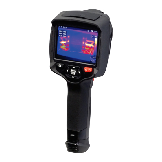
5. Structure Description 1 - Visual Camera 2 - lnfrared Camera Lens 3 - Focus Ring 4 - Dust Cover Lanyard Hole 5 - Trigger 6 - lnterface and Cover 6.1 - Type-C USB/Charge 6.2 - Micro SD Card Slot 7 - LCD Display and Touch Screen 8 - lmages Browse Button 9 - Power/Lock Button... -
Page 10: Before You Start
6. Before You Start 6.1. How to Charge the Battery • Before you use the Thermal Imager for the first time, charge the battery for three and a half hours. • The battery status shows on the six-segment charge indicator. •... -
Page 11: Power Off
6.3. Power Off • When the Thermal lmager turns on, Push and hold the Power/Lock " " Button for two seconds, then popup the power off menu, press "OK" to power off the device. • Push and hold the Power/Lock " "... -
Page 12: Lens
6.5. Lens • The Thermal Imager has a Lens. • FOV is the largest area that your Imager can see at a set distance. • This table lists the horizontal FOV, vertical FOV and IFOV for lens. Focal Length Horizontal FOV Vertical FOV IFOV 7.5mm... -
Page 13: Focus
6.6. Focus • To adjust focus, clockwise or Anti-clockwise rotates the IR Lens. • When target comes into focus, it shows a sharper image. • When the target moves out of focus, the thermal image becomes blurry. Note: Correct focus is important in all imaging applications. Correct focus makes sure that the infrared energy is correctly directed onto the pixels of the detector. -
Page 14: Emissitivity Adjustment
• This simplification does not work on shiny surfaces or unpainted metals as they have an emissivity of <0.6. These materials are not good at radiating energy and are classified as low emissivity. • To more accurately measure materials with a low emissivity, an emissivity correction is necessary. -
Page 15: Thermal Imager Reporter Software
• In most cases, the reflected temperature is identical to the ambient air temperature. • Only when objects with strong emissions with much higher temperature are in the proximity of the object being measured should be determined and used. • The reflected temperature has only little effect on objects with high emissivity. -
Page 16: Image Mode
Parameters: Parameters set for the calculation temperature. Measure Tools: Set for the calculation and display of radiometric temperature measurement data related to the thermal images. Image Mode: Set image source for the display on the Thermal Imager's LCD. It contains five items such as infrared image, visual image and fusion. - Page 17 AUF: Auto Fusion mode, Picture in Picture: Display fusion image of infrared and compare the centre area visible images. temperature with full screen, the machine will calculate the mix ratio of infrared and visible images automatically. Zoom Mode: In this mode, the image can be zoomed in/out continuously.
-
Page 18: Image Palette
7.3. lmage Palette • The Image Palette lets you change the false-colour presentation of the infrared images on display or captured. • A variety of palettes are available for specific applications. • The standard palettes offer an equal, linear presentation of colours that allow for best presentation of detail. -
Page 19: Image Adjustment
Zone Alarm: The temperature Visible Zone: The temperature between the high alarm and the between the high alarm and the low alarm set value will be low alarm set value will be coloured to orange. coloured to the palette, other part of the image will displayed as visible image. -
Page 20: Histogram Mode And Auto Mode
• Lock the low level and adjust the high level of the temperature range: • Lock the high level and adjust the low level of the temperature range: 7.4.2. Histogram Mode and Auto Mode • Auto Mode: level and span are decided by the thermal image of minimum temperature and maximum temperature. -
Page 21: Measurement Menu
7.5. Measurement Menu 1. ln main menu, press "Measurement" icon button, highlight "Measurement". 2. Press "Up" button, popup Image submenu which contains 5 kinds of Measurement tools. 3. Press "Left" or "Right" button, or touch the Measurement tools icons, highlight the Measurement tool which you want to choose. 4. -
Page 22: Ambient Temperature Composation
7.6.1. Ambient Temperature Composition • In Ambient temperature submenu, press "Left" and "Right" arrow to change the temperature values. • Ambient temperature will affect the measurement of the thermal imager, it can be composite from 0 degree to 50 degrees. 7.6.2. -
Page 23: Delta Temperature Compensation
7.6.4. Delta Temperature Compensation In delta temperature submenu, press "Left" and "Right" arrow to change the temperature values. 7.6.5. Distance • In distance submenu, press "Left" and "Right" arrow to change the distance values. • There are many substances in the air that can absorb infrared rays, so the infrared ray of the object will decrease as the distance increases. -
Page 24: Settings Menu
7.7. Settings Menu 1. ln main menu, press "Settings" icon button, highlight "Settings". 2. The Settings menu will display. 7.7.1. Device Settings There are multi pages in Device setting, use " " icon to go to next page, or use " " to go to previous page. Brightness: Drag the slider bar to adjust the LCD brightness. - Page 25 Time Date: Press " " or " " to change time/date, then press "Set Date" to save the change, or press "Cancel" to quit. Language: Press "Up/Down" Button to to select language and use "MENU/OK" Button to set selected language to be valid. Auto Power Off •...
-
Page 26: Measure Settings
7.7.2. Measure Setting • Select the "Measure Setting" menu, the Measure Setting menu will be displayed. • There are four options in the Measure setting menu, as shown in the following pictures: Distance Unit • Change the distance unit between "m" and "ft", "m"... -
Page 27: Reset
Image Align Press " " to adjust the vision’s position to align the vision and infrared. 7.7.3. Reset Format Memory Format Memory operation will format all the Picture Gallery, the device setting is not affected. -
Page 28: Camera Menu
Factory Settings Factory Settings of the Thermal lmager is as follows: Item Parameter Value Measurement Center Spot Measurement Hot Spot Measurement Cold Spot Measurement Measurement Parameters Emissivity 0.95 Reflective temperature Image Mode Infrared Palette Iron Adjustment Auto System Setting Language English HDMI Output Laser... -
Page 29: Add Text Note
7.8.2. Add Text Note • Touch the "Text information" icon, it can add some text information into the picture, • Next time if the saved picture is opened in gallery or PC software, the text info will displayed with the picture. -
Page 30: Change Colour
7.8.6. Change Color Touch the "Pallete" icon, it can change the image colour. 7.9. Video Menu The Thermal lmager has ".mp4"' video capture. 1. ln desktop, press Trigger button and hold for about 2 seconds, start video capture with voice. 2. -
Page 31: Play A Video
7.10.2. Play a Video When current file type is video, press " " to play video. 7.10.3. View Image Info Press " " to read the information of the current file. 7.10.4. Delete a File Press " " to delete the current file. 7.11. -
Page 32: Fault Diagnosis And Exclusion
8. Fault Diagnosis and Exclusion • If you encounter any problems while using the thermal imager, overhaul according to the following table. • If the problem persists, disconnect the power and contact withMajor tech’s technical support department. Phenomenon of the fault Cause of the fault Solution Thermal imager cannot turn on No battery... -
Page 33: Analyse
9.2.2. Analyse Select a IR Picture and click " " icon to analyse it. 1. lmage Mode Click " " icon to select image mode. There are four modes for you to select. IR Mode: only infrared picture displayed. Visible Mode: only visible picture displayed. IR Fusion Mode: The infrared picture is fusioned with visible picture. -
Page 34: Report And Share
3. Analyse Click " " icon to analyse the IR pictures. There are three analyse tools: Point Analyse: Add a point to the picture, it will display the temperature of the point. Line Analyse: Add a line to the picture. It will display the highest, lowest and average temperature of the line. -
Page 35: Pc Software
10. PC Software 10.1. System Required • Window XP or higher version of Windows system, please make sure you have installed Net Framework 2.0 or Net Framework 3.5 (Include 2.0) when you install PCIMeter software. • If not, please find and install Microsoft. NET_Framework_v2.0.exe that is provided to you. - Page 36 MAJOR TECH (PTY) LTD South Africa Australia www.major-tech.com www.majortech.com.au sales@major-tech.com info@majortech.com.au...
Need help?
Do you have a question about the MTi15 and is the answer not in the manual?
Questions and answers