Table of Contents
Advertisement
Quick Links
Advertisement
Table of Contents

Summary of Contents for Hydro-Gear 310-1500
- Page 1 310-1500/310-1700 Integrated Hydrostatic Transaxle Service and Repair Manual BLN-52178 December 2008 WMV- Digitally signed by WMV-Dresden DN: cn=WMV-Dresden, c=DE, o=WMV-Dresden, Dresden email=noreply@wmv-dresden.de Date: 2017.01.26 09:49:46 +01'00'...
-
Page 2: Table Of Contents
TABLE OF CONTENTS Section Page Foreword ..........................1 Description and Operation ....................2 Introduction .......................... 2 General Description ............................. 2 Introduction ..............................2 Hydraulic Schematic ..........................3-5 Product Identifi cation ........................... 6 Technical Specifi cations ..........................7 Safety ............................ 8 Personal Safety ............................ -
Page 3: Foreword
Service Dis trib u tor. Many dis trib u tors will be trou ble shoot ing the Hydro-Gear -1500 or -1700 host ing cer ti fi ca tion testing. These study guides Integrated Hydrostatic Transaxle (IHT). -
Page 4: Description And Operation
The purpose of this manual is to provide use- plate re vers es the fl ow of oil from the pump ful information for servicing the Hydro-Gear ® and thus re vers es the di rec tion of the motor -1500/ -1700 Integrated Hy dro stat ic Transaxles output ro ta tion. -
Page 5: Hydraulic Schematic
HYDRAULIC SCHEMATIC Figure 1. -1500 Hydraulic Schematic Figure 2. -1700 Hydraulic Schematic Figure 3. -1700 Hydraulic Schematic with Auxiliary Pump -1500/-1700 IHT... - Page 6 HYDRAULIC SCHEMATIC Figures 4 and 5 provide illustrations of the hy- to the trans mis sion housing and must be made drau lic oil circuit. The oil supply for the hy drau lic up in the loop. A charge pump is included on sys tem of the IHT is also utilized for the lu bri - the IHT to supply this makeup fl...
- Page 7 HYDRAULIC SCHEMATIC Figure 5. -1700 Hydraulic Flow Illustration -1500/-1700 IHT...
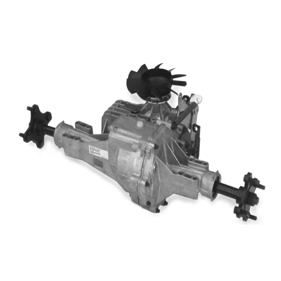
- Page 8 EXTERNAL FEATURES -1500 AND -1700 -1500/-1700 IHT...
-
Page 9: Product Identification
-1700 IHT can be de ter mined from the la bel shown in Fig ure 6. H Y D R O - G E A R SULLIVAN, IL. U.S.A. I IIII III IIII II II Model Model OEM Model Hydro-Gear 312-1700 165758 310-3000 Ref er ence Number Number Number Number... -
Page 10: Safety
SECTION 2. SAFETY This symbol points out important Wear appropriate clothing. Loose or hanging safe ty instructions which, if not followed, could clothing or jewelry can be hazardous. Use the en dan ger the personal safety and/or property ap pro pri ate safety equipment, such as eye of your self and others. -
Page 11: Troubleshooting
SECTION 3. TROU BLE SHOOT ING In many cases problems with the IHT are not re- WARNING lat ed to a de fec tive trans mis sion or axle, but are caused by slip ping drive belts, par tial ly en gaged Do not attempt any ser vic ing or ad- bypass valves, and loose or dam aged control just ments with the engine run ning. -
Page 12: Service And Maintenance
Hydro-Gear product un- ® 6. Inspect the vehicle control linkage to the less the ser vic ing deal er is a cur rent di rec tion al control arm on transaxle. -
Page 13: Fluids
FLUID CHANGE FLUIDS The fl uids used in Hydro-Gear ® products have This transaxle is factory fi lled and does not been carefully selected, and only equivalent, or re quire a regular oil change. In the event of better prod ucts should be sub sti tut ed. -
Page 14: Brake Maintnenance
BRAKE MAINTENANCE BRAKE SETTING 1. Remove the brake arm bias spring, and then the cotter pin securing the brake castle nut. 2. Insert a 0.015" (.381 mm) feeler gage be- tween the brake disc and top brake puck, and then set the brake by tightening or loos en ing the cas tle nut. -
Page 15: Return To Neutral Setting Foot Control
RETURN TO NEUTRAL SETTING FOOT CONTROL 3. Start the engine and increase the throttle to WARNING full engine rpm. 4. Check for axle rotation. If the axles do not POTENTIAL FOR SERIOUS IN JU RY ro tate, go to Step 5. If the axles rotate, go to Step 6. -
Page 16: Purging Procedures
PURGING PROCEDURES Due to the effects air has on effi ciency in hy- 1. With the bypass valve open and the engine dro stat ic drive applications, it is critical that it run ning, slowly move the directional control be purged from the system. in both forward and reverse directions 6 to 10 times, as air is purged from the unit, the These purge procedures should be im ple -... -
Page 17: Repair
It is necessary to remove the -1500 or -1700 prov al be fore con duct ing main te nance from the ve hi cle before performing the repair of a Hydro-Gear product un less the ® pro ce dures pre sent ed in this section. Use the... -
Page 18: How To Use This Manual
HOW TO USE THIS MANUAL Many of the parts and subassemblies of this Subassemblies removed to reach another transaxle can be removed and serviced in de - com po nent or feature need not be fully dis- pen dent ly of other components. The dis as - as sem bled. -
Page 19: Brake Assembly
BRAKE ASSEMBLY Refer to Figures 12 and 13. 4. Remove upper bolt (121) which secures brake yoke assembly (122). DISASSEMBLY 5. Remove lower bolt (132), washer (139) and 1. Remove the cotter pin (129), castle nut spacer (130) which se cure the brake yoke (128), and wash er (77). - Page 20 INSPECTION 1. Inspect the brake pucks (120) for excessive 6. Install brake anti-drag compression spring wear. (151), and two brake pins (125). 2. Replace with new if necessary. 7. Install brake arm (124) onto brake yoke as- sem bly. ASSEMBLY 8.
-
Page 21: Bypass Assembly
BYPASS ASSEMBLY Refer to Figure 14. DISASSEMBLY 1. Remove retaining ring (42). 2. Remove bypass arm (41). 3. Remove bypass lip seal (40). INSPECTION 1. Inspect bypass arm (41) for wear. ASSEMBLY 1. Install bypass lip seal (40). See Page 25 for REF. -
Page 22: Control Assembly
CONTROL ARM ASSEMBLY Refer to Figure 15, Page 21 ASSEMBLY DISASSEMBLY CONTROL ARM ASSEMBLY RETURN TO NEUTRAL ASSEMBLY 1. Install new trunnion arm lip seal (33), into main housing (1). See page 22 for in struc - 1. Remove screw (88) and adjusting puck tions. - Page 23 REF. Part Name REF. Part Name 26 Control Arm 87 Washer 31 Trunnion Arm 88 Screw 32 Trunnion Bushing 89 Bearing 33 Lip Seal 90 Locating Spacer 34 Return Arm 92 Countersink Screw 36 Stud 95 Locknut 46 Spring 106 Trunnion Spacer 48 Adjusting Puck Figure 15.
-
Page 24: Seal Kit Replacement
SEAL KIT REPLACEMENT Before disassembly, wipe the unit free of any debris to avoid contamination. Refer to Fig ure 16. REF. Part Name 1 Main Housing 5 Lip Seal 7 Retaining Ring 33 Lip Seal 40 Lip Seal 41 Bypass Arm 42 Retaining Ring 75 Seal 84 Lip Seal... -
Page 25: Torque Bracket Assembly
TORQUE BRACKET ASSEMBLY (IF EQUIPPED) Refer to Figure 17. DISASSEMBLY 1. Remove lock nut (142), and bolt (143), from torque brack et (102). 2. Remove torque bracket (102), from main hous ing (1). ASSEMBLY REF. Part Name 1. Install torque bracket (102), onto main hous- 1 Main Housing ing (1). -
Page 26: Fan And Pulley Assembly
FAN AND PULLEY ASSEMBLY Refer to Figure 18. DISASSEMBLY 1. Remove jam nut (115) and slotted washer (107) from in put shaft (12). 2. Remove fan/pulley assembly (104) and (103). INSPECTION 1. Inspect fan (104) for broken and/or dam aged blades. -
Page 27: Input Shaft Assembly
INPUT SHAFT ASSEMBLY Refer to Figure 19. REF. Part Name DISASSEMBLY 1 Main Housing 4 Spacer 5 Lip Seal 1. Drain the oil from the transaxle by opening 6 Wire Retaining Ring the fi ll port or level port and positioning the 7 Snap Ring unit so the oil drains. -
Page 28: Auxiliary Pump
AUXILIARY PUMP ASSEMBLY (IF EQUIPPED) Refer to Figure 20. DISASSEMBLY 1. Remove two screws (29) from the auxiliary pump cover (54), and remove the cover (54). 2. Remove o-ring (53), gerotor assembly (52), shim (162) and pins (163). INSPECTION REF. Part Name 1. -
Page 29: Charge Pump Assembly
CHARGE PUMP ASSEMBLY LOWER HOUSING/FILTER (IF EQUIPPED) ASSEMBLY (-1500) Refer to Figure 21. Refer to Figure 22. DISASSEMBLY DISASSEMBLY NOTE: Before disassembling, note the 1. Remove the eleven housing screws (50) and orientation of the charge pump cover low er cover (51), and remove sealant from (54). -
Page 30: Lower Housing/Filter/Manifold Assembly
LOWER HOUSING/FILTER/ 8. Secure lower cover (51) to main housing (1) by in stall ing the eleven housing screws MANIFOLD ASSEMBLY (50), reference Table 5, Page 17. -1700 (STANDARD CHARGE PUMP) Refer to Figure 23. NOTE: Charge Pump assembly must be removed before the following steps can be performed. - Page 31 LOWER HOUSING/FILTER/ MANIFOLD ASSEMBLY/ -1700 (AUXILIARY CHARGE PUMP) Refer to Figure 23A. NOTE: Charge Pump assembly must be removed before the following steps can be performed. See page 26. DISASSEMBLY 1. Remove the eleven housing screws (50) and low er cover (51), and remove sealant. 2.
-
Page 32: Planetary Differential Assembly
PLANETARY DIFFERENTIAL 16. See page 22 for axle shaft seal removal. ASSEMBLY W/O DIFF. LOCK INSPECTION Refer to Figure 24, next page. 1. Inspect all gears for excessive wear or dam- age and re place if necessary. NOTE: Brake Assembly, and optional Return to Neutral have to be re moved 2. - Page 33 REF. Part Name 1 Main Housing 2 R.H. Housing Assembly 58 Carrier Pin 59 Planetary Gears 60 64T Spur Gear 61 21T Sun Gear 62 Planetary Thrust Plate REF. Part Name 63 51T Ring Gear 69 Flange Bearing 64 Planetary Carrier 71 Wash er REF.
- Page 34 PLANETARY DIFFERENTIAL 18. Remove differential components washer guide (177), relief springs (145), dogs (175), ASSEMBLY W/ DIFF. LOCK load plate (173), washer (172), rotating cam (171) and stationary cam (170). Refer to Figure 25, next page. INSPECTION NOTE: Brake Assembly, and optional 1.
- Page 35 REF. Part Name 1 Main Housing 2 R.H. Housing Assembly 58 Carrier Pin 59 Planetary Gears 60 64T Spur Gear REF. Part Name 61 21T Sun Gear 96 Bearing Sleeve 62 Planetary Thrust Plate 117 Housing Pin 63 51T Ring Gear 118 Axle Hub Assembly 64 Planetary Carrier 119 Hex Nut...
-
Page 36: Motor/Center Section/Pump Assembly
INSPECTION MOTOR/CENTER SECTION/ 1. Inspect running surface of thrust bearing PUMP ASSEMBLY (25) for ex ces sive wear. Refer to Figures 26 and 27, (next pages). 2. Inspect each piston (23), spring (18), and pis ton seat (22) in the mo tor cylinder block NOTE: Brake Assembly, Charge Pump as sem bly. - Page 37 7. In stall cen ter sec tion as sem bly (3) into main 13. Using the assembly tool to compress pis tons housing (1). Make sure center sec tion seats (22), install motor cylinder block as sem bly fully on its mating sur face. (21).
- Page 38 REF. Part Name REF. Part Name REF. Part Name 1 Main Housing 20 Bushing 3 Center Section Assembly 21 21cc Cylinder Block 39 Bypass Actuator 13 Block Washer 22 Pistons 43 Pin 14 Block Spring 23 Springs 44 Screws 15 10cc Cylinder Block 24 Motor Shaft 53 O-Ring 16 Pistons...
-
Page 39: Directional Control Assembly
DIRECTIONAL CONTROL ASSEMBLY Refer to Figure 28. NOTE: The Motor/Center Section/Pump Assembly must be disassembled before this procedure can be completed. DISASSEMBLY 1. Remove swashplate assembly (10). Dis as- REF. Part Name sem ble swashplate assembly by removing 1 Main Housing thrust bearing (11) from swashplate (10). -
Page 40: Transaxle Installation
TRANSAXLE INSTALLATION ASSEMBLY AFTER A COMPLETE TEAR-DOWN Use the following pro ce dure to complete in stal - la tion of the transaxle on the ve hi cle. If the unit has been torn down completely, the fol low ing sum ma ry identifies the assembly 1. -
Page 41: Sealant Application
SEALANT APPLICATION NOTE: Prior to applying the new sealant, the old sealant must be removed from all surfaces. A small consistent bead of the sealant around the housing face will be suffi cient. Use spar- ing ly. The illustration below illustrates the correct ar eas. -
Page 42: Parts List
Figure 31. IHT -1500 Exploded View -1500/-1700 IHT... - Page 43 ITEMS LIST -1500 Part numbers are not provided in this manual. See CD (BLN-51427) for part num bers. DESCRIPTION DESCRIPTION Main Housing Assembly Shaft, Axle R.H. Housing Assembly Washer Brake Bolt Kit Gasket Material/Sealant Center Section Assembly Torx Head Screw 5/16 - 18 Spacer Needle Bearing Lip Seal...
- Page 44 Figure 32. IHT -1700 Exploded View -1500/-1700 IHT...
- Page 45 ITEMS LIST -1700 Part numbers are not provided in this manual. See CD (BLN-51427) for part numbers. DESCRIPTION DESCRIPTION Main Housing Assembly R.H. Housing Assembly Washer Brake Bolt Kit Washer Center Section Assembly Screw 5/16 - 24 X 1-3/4 Spacer Bearing Lip Seal Spacer, Locating...
-
Page 46: Glossary Of Terms
SECTION 6. GLOSSARY OF TERMS Axial Piston: Type of design for hydraulic motors and pumps in which the pistons are arranged parallel with the spindle (input or output shaft). Bypass Valve: A valve whose primary function is to open a path for the fl uid to bypass the motor or pump. - Page 47 Hydrostatic Transaxle: A multicomponent as sem bly including a gear case and a hydrostatic trans mis sion. Hydrostatic Transmission: The combination of a hy drau lic pump and motor in one housing to form a de vice for the control and transference of power. Inlet Line: A supply line to the pump.
- Page 48 © 2008 HYDRO-GEAR Printed in U.S.A. Rev. P1...
Need help?
Do you have a question about the 310-1500 and is the answer not in the manual?
Questions and answers