
Summary of Contents for DINA Elektronik SAFEONE DN3PR1
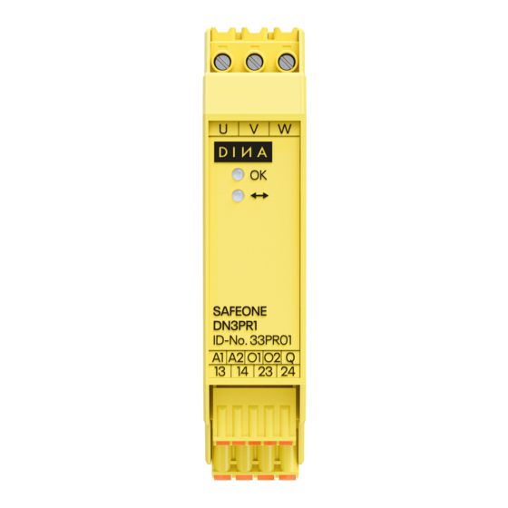
- Page 1 SAFEONE DN3PR1 Hardware Safety module for sensorless detection of direction of rotation dina.de...
- Page 2 Mail info@dina.de www.dina.de © Copyright by DINA Elektronik GmbH 2021 All parts of this documentation are protected by copyright. Any use beyond that permitted under copyright law is not permitted without express written con- sent from the publisher. This applies in particular to the reproduction, distribution and translation of this documentation or parts thereof, as well as the storage and processing of this content using electronic data processing systems.
-
Page 3: Table Of Contents
Retrofitting and conversion 2.5.2 Basic safety regulations Working on live parts 3 EC declaration of conformity 4 Function description Acknowledge Input Signal outputs Pin assignment Block diagram 5 Launch 6 Diagnostics 7 Example of application 8 Order data Hardware Manual SAFEONE DN3PR1... - Page 4 Contact outputs General data Connection data Environmental conditions Dimensions 9.10 Safety-related parameters in accordance with DIN EN ISO 13849-1:2016-06 9.11 Relay load curve 10 Installation and removal 10.1 Installation a module 10.1.1 Overview 10.2 Removing module Hardware Manual SAFEONE DN3PR1...
-
Page 5: Structure Of The Document
Indicates an item in a list. 1.1.3 Emphasizing words using typography The following typography is used to emphasize words with special functions: Represents a numbered item in a figure. Indicates a cross-reference to another page, figure or document. Hardware Manual SAFEONE DN3PR1... - Page 6 We do all we can to provide complete, accurate documentation for the product. If you have any suggestions for improvement or advice for us, please share your thoughts with us. Send us your comments by e-mail to the following address. E-Mail: info@dina.de Hardware Manual SAFEONE DN3PR1...
-
Page 7: Safety
For a potentially hazardous situation that could result in injuries. CAUTION For a potentially harmful situation in which the product or an item near it could be damaged. CAUTION For a hazard that could cause environmental damage. Hardware Manual SAFEONE DN3PR1... -
Page 8: Hazard Symbols
Electric shock – dangerous voltage! Qualification of personnel DINA Elektronik GmbH distinguishes between specialist staff with different qualifications when it comes to carrying out work on the product. The minimum required qualifications are specified for each task and are defined as follows: 2.2.1... -
Page 9: Intended Use And Improper Use
With PLe, Sil 3, Cat. 3: The motor must be switched torqueless for at least 5 s once a day. With Pld, Sil 2, Cat. 3: The motor must be switched torqueless for at least 5 s once quarterly. Hardware Manual SAFEONE DN3PR1... -
Page 10: Documentation
Safety regulations The safety regulations listed below must always be complied with. In the event that these safety regulations are not complied with or the device is used improperly, DINA Elektronik GmbH accepts no liability for any resulting injury or damage. -
Page 11: Retrofitting And Conversion
Basic safety regulations The safety regulations listed below must always be complied with. In the event that these safety regulations are not complied with or the device is used improperly, DINA Elektronik GmbH accepts no liability for any resulting injury or damage. -
Page 12: Working On Live Parts
Safety • DINA Elektronik GmbH is not able to make any guarantees regarding the properties of an overall system not designed by the company. • DINA Elektronik GmbH accepts no liability for any recommendations given or implied in the following description. -
Page 13: Ec Declaration Of Conformity
Am Grauen Stein 51105 Köln Germany NB 0035 Bevollmächtigter für die Zusammenstellung der technischen Unterlagen/ Authorized representative for the compilation of the technical documents DINA Elektronik GmbH Esslinger Str. 84 72649 Wolfschlugen Deutschland Stefan Najib Geschäftsführer/CEO Wolfschlugen, 06.11.2020 Hardware Manual SAFEONE DN3PR1... -
Page 14: Function Description
• potential-bound • short circuit and overload protection • not safety-related The output O1 indicates the state of the enabling current path. The output O2 indicates the operational readiness. This switches off in case of an error. Hardware Manual SAFEONE DN3PR1... -
Page 15: Pin Assignment
Acknowledgment input for manual, monitored starting. Digital positive switching semiconductor outputs for the O1, O2 transmission of switch-ing states to a higher-level control for diagnostic tasks. 13-14/23-24 Enabling contacts (2 NO-contacts) OK-LED Operational readiness State of the enabling current path 13-14/23-24 Hardware Manual SAFEONE DN3PR1... -
Page 16: Block Diagram
Launch Block diagram Measuring inputs Inputs Outputs Hardware Manual SAFEONE DN3PR1... -
Page 17: Diagnostics
"OK" LED on the device. The flashing code is repeated continuously with a pause of 1 s. The meaning of the individual flashing codes can be found in the table. Hardware Manual SAFEONE DN3PR1... - Page 18 Check the wiring at the measuring inputs for Error phase shift flash • Wire break Relay error Send the device to DINA Elektronik for testing. flash Check the wiring at the measuring inputs for • Short circuit Single-channel error flash •...
-
Page 19: Example Of Application
The acknowledgment button S1 is used to reset the safety function after safety function the motor turns again in the preferred direction. Monitoring of external The external, positively driven contactors K1, K2 are integrated in the start contactors circuit of the safety switching device. Hardware Manual SAFEONE DN3PR1... -
Page 20: Order Data
24V DC (-15/+10%) Current < 5,0 mA Power consumption typ. 4 mA (at U Measuring inputs Measuring inputs U, V, W Voltage 90V AC to 480V AC (phase to phase) Power consumption 0,24mA to 480V AC Maximum frequency 1200Hz Hardware Manual SAFEONE DN3PR1... -
Page 21: Signal Outputs
6 A gL/gG AC15: 5A/230V AC, >2x10 switching cycles B10d values acc. to AC1: 6A/230V AC, >2x10 switching cycles DIN EN 61810-2-1, 01.2012 DC13: 4A/24V DC, >3x10 switching cycles DC1: 6A/ 24V DC, >7x10 switching cycles Hardware Manual SAFEONE DN3PR1... -
Page 22: General Data
Push-in terminals Screw Number of positions 0,25 – 0,25 Connection cross-section 0,25 – 2,5mm 2,5mm -1,5mm Connection cross-section AWG 24…12 24…16 24…12 Tightening torque 0,5Nm/0,6Nm Connection wire Only 60/75°C copper Environmental conditions Operating temperature -20°C to +55°C Hardware Manual SAFEONE DN3PR1... -
Page 23: Dimensions
2 cycles/h 1,16 x 10 5A AC15 2 cycles/h 1,87 x 10 9.11 Relay load curve Ohmic and inductive load for the enabling NO-contacts 13/14 und 23/24 ohmic load L/R = 0ms inductive load L/R = 40ms Hardware Manual SAFEONE DN3PR1... -
Page 24: Installation And Removal
The locking slider engages under the rail. 10.2 Removing module Procedure Use a screwdriver to move the locking slider away from the module. Move the module upward and remove it from the rail. Hardware Manual SAFEONE DN3PR1...
Need help?
Do you have a question about the SAFEONE DN3PR1 and is the answer not in the manual?
Questions and answers