Table of Contents
Advertisement
Quick Links
Advertisement
Table of Contents

Related Manuals for Festo PDAD


Summary of Contents for Festo PDAD
- Page 1 PDAD Adsorption dryer Operating instruc- tions 8167686 2022-02i [8167688]...
- Page 2 Translation of the original instructions Hirschmann is a registered trademark of its respective trademark holder in certain countries. ®...
-
Page 3: Table Of Contents
Main components PDAD-100 ........ - Page 4 10.1 Nominal flow rate ............36 Festo — PDAD — 2022-02i...
-
Page 5: About This Document
About this document About this document Applicable documents All available documents for the product è www.festo.com/sp. Document Product Contents Assembly instruc- Service kit PDAD-…-SP12000 Replacing the drying agent cartridges tions Tab. 1: Applicable documents Product labelling • Observe the specifications on the product. -
Page 6: Safety
– Observe the identifications on the product. – Take into account the ambient conditions at the location of use. – Before working on the product, switch off the power supply and secure it against being switched on again. Festo — PDAD — 2022-02i... -
Page 7: Intended Use
The qualified personnel must be familiar with the installation of electrical and pneumatic control systems. Additional information – Contact the regional Festo contact if you have technical problems.è www.festo.com. – Accessories and spare parts è www.festo.com/catalogue. Festo — PDAD — 2022-02i... -
Page 8: Product Overview
Adsorption dryer PDAD Tubing PDAD operating DC power supply instructions socket (grey) Tab. 6: Scope of delivery PDAD The dryer is supplied in protective packaging. 4.1.2 Not in scope of delivery Accessories Type Service kit with drying agent cartridges, O-... -
Page 9: Function
After a further 50 s, the regeneration cycle of the other air reservoir is started at the start of the new operating cycle. Festo — PDAD — 2022-02i... -
Page 10: Structure
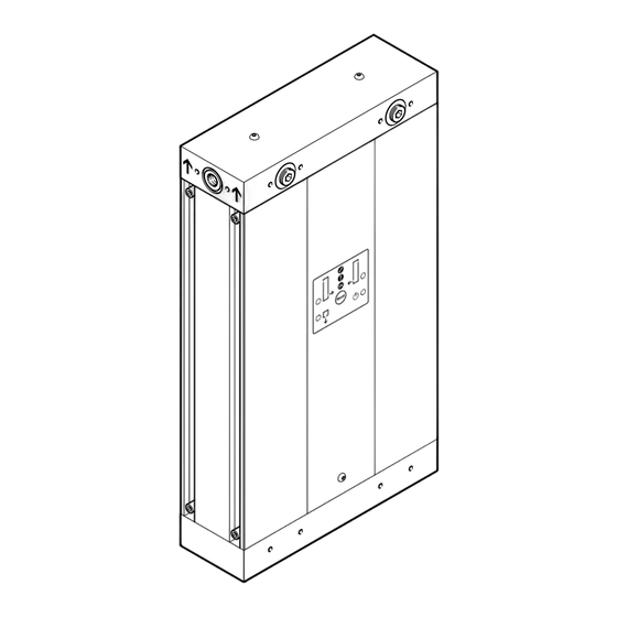
Air gun nozzle Air reservoir Upper valve block Drying agent cartridge Multi-way distributors Lower valve block Cover sheet Base plate Rear covering Covering retaining screw Mains connection on the back of the device Front covering Festo — PDAD — 2022-02i... -
Page 11: Main Components Pdad-100
Upper valve block Drying agent cartridge Multi-way distributors Lower valve block Cover sheet Base plate Screw and seal for connection of multi-way distributor Covering retaining screw Rear covering Front covering Power connection inside the device Festo — PDAD — 2022-02i... -
Page 12: Electronic Controller
è 8.4 Replacing air gun nozzle. The following table è Tab. 8 Required air gun nozzleshows the numbers of the required air gun nozzles for the possible operating pressures. Festo — PDAD — 2022-02i... -
Page 13: Display Components
è 10.1 Nominal flow rate. 4.3.9 Display components Electronic control panel LED X, left air reservoir LED Y, right air reservoir LED POWER, power supply LED Z, condensate drain Fig. 3: Control panel LEDs Festo — PDAD — 2022-02i... -
Page 14: Assembly
The 3 ports at the output are on the right. Any one of the 3 input and output ports can be used. The ports that are not used must be closed with the supplied sealing plugs. Festo — PDAD — 2022-02i... - Page 15 Assembly All 3 output openings can be used. Festo recommends connecting a check valve to every output in use. Only one input port may be used. Input side Output side Display of flow direction display (arrows) Fig. 4: Multi-way distributor - configuration of...
- Page 16 Fasten the multi-way distributor with 4 retaining screws (A/F 5). – Maximum tightening torque 20 Nm. 4. Position the cover and fasten with the 2 retaining screws. – Maximum tightening torque 1 Nm. Festo — PDAD — 2022-02i...
-
Page 17: Assembly
(± 5°). There must be sufficient space under the filter bowl (≥ 100 mm). If installed in a horizontal position, the dryer must be supported with suitable material. Vertical Horizontal Tab. 10: Permitted mounting positions Festo — PDAD — 2022-02i... - Page 18 3. Mount the module connector plate [1] on the input with the hollow bolt [4]. The module connector plate can offset 90° for installation of the dryer in a horizontal position. Type Pneumatic port Width across Tightening torque flats PDAD-...-G3/8 G 3/8 Max. 15 Nm PDAD-...-G1/2 G 1/2 Max. 18 Nm Festo — PDAD — 2022-02i...
-
Page 19: Condensate Input And Condensate Output
Condensate input and condensate output The ports for the condensate input and output are located at the rear of the adsorption dryer. Depending on the circumstances, it may make sense to make the connection before installing the adsorption dryer. Festo — PDAD — 2022-02i... -
Page 20: Installing Mounting Accessories
5. Fasten the tubing to the drain point to prevent the tubing from whipping during the drainage process. Installing mounting accessories The mounting accessories are not included in the scope of delivery of the adsorption dryer PDAD. Wall mounting ABMW-PDAD Foot mounting ABMF-PDAD Tightening torque: max. -
Page 21: Installation
The cables must meet the requirements of EN 61010-1 for reinforced insulation. A special power supply socket is supplied for each type of current. The power supply sockets have a different number of contacts for mechanical coding. Festo — PDAD — 2022-02i... - Page 22 Alternating current (AC) power connection Power connection for direct current (DC) Tab. 15: Alternate power connections (use only one connection at a time) The connection for the supply voltage on the PDAD-100 is located under the rear covering. Festo — PDAD — 2022-02i...
- Page 23 Reference potential for the power supply – reserved, do not connect n. c. Not connected. The device is double insulated and therefore does not require earthing (protection class II). Tab. 17: Power connection for direct current (DC) on the device Festo — PDAD — 2022-02i...
-
Page 24: Connection Alarm
è Tab. 17 Power connection for direct current (DC) on the device. Connection ALARM An alarm device can be connected to the ALARM connection è 4.3.7 Alarm relay. Alarm device, visual or audible External power supply Fig. 11: Connection of an alarm device Festo — PDAD — 2022-02i... -
Page 25: Em Connection
5. Fasten the covering. Make sure the seal and screw are seated correctly. EM connection The EM connection is reserved for later extensions. The installed junction box is bridged internally. Do not remove the junction box. Festo — PDAD — 2022-02i... -
Page 26: Commissioning
5. Switch on the power supply. Ä The four LEDs on the display panel simultaneously flash green four times and then red four times. The device is ready for operation. The factory-set operating cycle starts automatically. Festo — PDAD — 2022-02i... -
Page 27: Resetting The Electronic Controller
è 8.4 Replacing air gun nozzle Clean the silencer. è 8.6 Cleaning the silencer Replace the drying agent cartridge. every 12000 operating See assembly instructions for hours service kit è 1.1 Applicable docu- ments Tab. 21: Overview of maintenance work Festo — PDAD — 2022-02i... -
Page 28: Shut Down The Device
The covering must be removed for maintenance work on the air gun nozzle and silencer. The covering is fastened at the top with a spring insert and secured at the bottom with a screw. The PDAD-100 has an additional screw in the upper part. -
Page 29: Replacing Air Gun Nozzle
Maintenance 3. PDAD-100: unscrew the top retaining screw. 4. Pull the covering outwards and remove it from below. Mounting covering 1. Insert the covering with the connector spring into the slot of the dryer. 2. PDAD-100: tighten the top retaining screw. - Page 30 Maintenance 2. PDAD-100 only: remove the front and rear covering è 8.3 Remove covering and mount. The air gun nozzle is located in the upper valve block. 3. Unscrew the retaining screw of the air gun nozzle. 4. Pull the air gun nozzle out of the opening in the top valve block.
-
Page 31: Cleaning The Air Gun Nozzle
1. Shut down the device è 8.2 Shut down the device. 2. PDAD-100 only: remove the front and rear covering è 8.3 Remove covering and mount. 3. Disconnect the silencer from the bottom valve block and remove it from the dryer. -
Page 32: Malfunctions
– Ensure the minimum pressure. Input pressure too low – Check the input temperature and Input temperature too high ambient temperature, comply with the operating conditions. – Clean or replace the silencer. Silencer clogged or damaged Festo — PDAD — 2022-02i... - Page 33 – Shut down the Condensate LED Z flashes Solenoid valve for condensate drain does not drain open or short circuit device. – Contact Festo switch LED POWER Error in electronic controller Service. flashes red Tab. 23: Electrical diagnostics Festo — PDAD — 2022-02i...
-
Page 34: Diagnostics Via Led
Mounting position Vertical or horizontal è Tab. 10 Permitted mounting positions Relative humidity, envi- 80% at temperatures up to 31 °C, decreasing linearly to 50% at ronment 40 °C. Max. setup altitude 2000 above IHRS Festo — PDAD — 2022-02i... - Page 35 Compressed air in accordance with ISO 8573-1:2010 [2:2:2], pres- sure dew point –40 °C Internal volume 11.0 15.8 22.0 Electrical - data of the integrated electrical controller Degree of protection IP65 in accordance with EN 60529 Protection class Pollution degree Festo — PDAD — 2022-02i...
-
Page 36: Nominal Flow Rate
728.5 994.3 Operating pressure 0.8 MPa, 8 bar, 116 psi Input [l/min] 132.5 197.9 336.4 752.0 1108.3 1484.3 Purge air [l/min] 36.0 54.0 97.0 194.5 302.0 389.0 Output [l/min] 96.5 143.9 239.4 557.5 806.3 1095.3 Festo — PDAD — 2022-02i... - Page 37 1589.4 2126.2 Operating pressure 1.5 MPa, 15 bar, 217.5 psi Input [l/min] 235.6 353.4 600.8 1342.9 1979.1 2650.5 Purge air [l/min] 34.0 71.0 103.0 182.5 282.0 365.0 Output [l/min] 201.6 282.4 497.8 1160.4 1697.1 2285.5 Festo — PDAD — 2022-02i...
- Page 38 1423.5 2097.8 2809.6 Purge air [l/min] 36.0 76.0 111.0 201.5 301.0 403.0 Output [l/min] 214.3 298.6 525.8 1222.0 1796.8 2406.6 Tab. 26: Nominal flow rate –40 °C pressure dew point, input temperature 25 °C saturated Festo — PDAD — 2022-02i...
- Page 39 704.4 945.6 Operating pressure 1.1 MPa, 11 bar, 159.5 psi Input [l/min] 123.7 185.5 315.4 705.0 1039.0 1391.5 Purge air [l/min] 34.0 49.0 96.0 182.5 272.0 365.0 Output [l/min] 89.7 136.5 219.4 522.5 767.0 1026.5 Festo — PDAD — 2022-02i...
- Page 40 998.8 1471.9 1971.3 Purge air [l/min] 36.0 76.0 111.0 201.5 301.0 403.0 Output [l/min] 139.2 186.8 335.8 797.3 1170.9 1568.3 Tab. 27: Nominal flow rate –70 °C pressure dew point, input temperature 25 °C saturated Festo — PDAD — 2022-02i...
- Page 42 Copyright: Festo SE & Co. KG 73734 Esslingen Ruiter Straße 82 Deutschland Phone: +49 711 347-0 Internet: © 2022 all rights reserved to Festo SE & Co. KG www.festo.com...
Need help?
Do you have a question about the PDAD and is the answer not in the manual?
Questions and answers