Advertisement
Quick Links
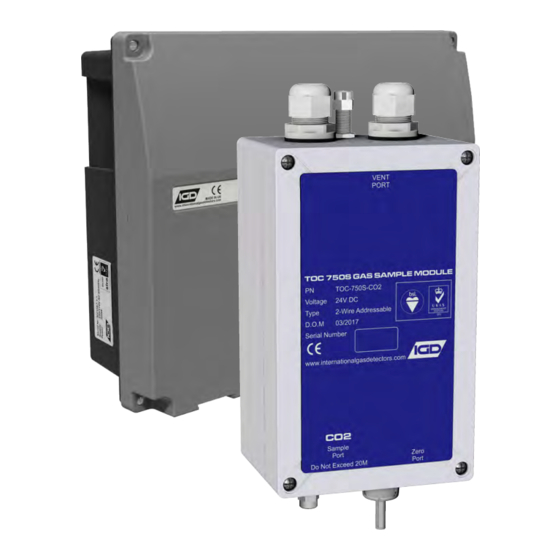
Sampler Module
Operation Manual
Document Ref: SL-065 v1.2
2-Wire
Addressable
2-WIRE SYSTEMS
SAMPLER MODULES
FS646773
internationalgasdetectors.com
+44 (0)161 483 1415
@
sales@internationalgasdetectors.com
EMS696504
/international-gas-detectors-ltd
Doc Ref: SL-065 v1.2 pg 1
Triton House
Crosby Street
Stockport
SK2 6SH
Advertisement

Summary of Contents for IGD TOC-750S-CO
- Page 1 Sampler Module Operation Manual Doc Ref: SL-065 v1.2 pg 1 Document Ref: SL-065 v1.2 2-Wire 2-WIRE SYSTEMS Addressable SAMPLER MODULES Triton House internationalgasdetectors.com +44 (0)161 483 1415 Crosby Street sales@internationalgasdetectors.com Stockport FS646773 EMS696504 /international-gas-detectors-ltd SK2 6SH...
- Page 2 4 off SSR Outputs (Switched Neg 24V DC, Common 200mA load shared across all O/P’s) 4 off SSR Outputs OP1 Dedicated to Low Flow Comms IGD Sentinel+ 2-Wire Protocol Temperature -5 to 55 Deg C Full Specification. Humidity 0-95% RH Non-Condensing...
- Page 3 90 mm Mounting Holes 122 mm Sample and exhaust ports suit 6mm OD x 4mm ID Soft tubing. IGD Part Number TOC-750S-TBE supplied as 20M coils. Samplers are designed for ambient sampling only Only use conduit/cable entries provided, drilling the enclosure will void any warranty...
- Page 4 Tube work should not allow condensing liquids to trap in the pipework. Where a large amount of condensation may occur consider fitting line traps. Contact IGD for further advice. A variety of End of Line Termination Points Are Available Contact IGD For...
- Page 5 Tocsin 750 Series Addressable Sample Modules are designed to sample using 6mm OD x 4mm ID tubing from locations up to 20M distant from the module. IGD provide EOL (End Of Line) filter modules to prevent dirt and debris from being drawn into the system.
- Page 6 Part Number TOC-750S-PN3 Where termination is required through into cold stores or wet environments IGD advise use of this part number. The rigid tube assembly passes through the wall of the process at an angle. The diameter and angle are chosen to ensure condensed liquids cannot be drawn up into the sampler assembly.
- Page 7 Doc Ref: SL-065 v1.2 pg 7 Overview Vent Port, Do Not Block Note depending on the nature of the sample it may be necessary to vent the spill gases to a safe location. Function Buttons and LED’s 1 2 3 4 5 DOWN SSR 1 Dedicated Fault SSR 2...
- Page 8 Addressing the Assembly Using the Function Buttons and LED’s Doc Ref: SL-065 v1.2 pg 8 The TOC-750 Module PCB is an Addressable Device and Comes Equipped With a Simple Interface to Allow the Base Address to be Set. To Set The Set Address, 1 2 3 4 5 DOWN Press and hold the Down button for >2s...
- Page 9 Doc Ref: SL-065 v1.2 pg 9 IGD provide a range of Android based Apps for use with suitable tablets and mobile phones. For control panels these connect directly using bluetooth. For addressable devices it is necessary to make a direct USB cable connection using IGD’s interface cable as indicated below.
- Page 10 Setup Channels Option Doc Ref: SL-065 v1.2 pg 10 This menu selection gives access to pump settings as follows: Use to turn pump on/off Use to view pump running Manual pump adjustment to pressure difference on to off fine tune using attached and to ensure pump starts flowmeter.
- Page 11 Setup Auto Zero/Calibration and Purge Settings Doc Ref: SL-065 v1.2 pg 11 Sample time is the period in seconds that the system runs for before either: Running an auto zero Running an auto calibration (Oxygen samplers) Turning pump off for 10s for the system to check ambient pressure ** Note there are selections mentioned against both the sample and zero pumps, ensure correct pump is...
- Page 12 Zero and Calibration Doc Ref: SL-065 v1.2 pg 12 The following diagram shows the preferred method to introduce zero and calibration gases to the sampler. The sampler must not be over or under pressurised during the zero or calibration process. With this arrangement set the flow rate from the gas cylinder such that the flowmeter shows 0.5L/Min of gas flow spilling off.
- Page 13 Zero and Calibration Doc Ref: SL-065 v1.2 pg 13 Flow a suitable zero gas (usually Nitrogen) allow the graph/reading to settle (usually 60-90 seconds) and select ZERO to zero the detector Now apply calibration gas as indicated. The graph should show the signal rise as the detector responds to gas and gives a visual indication to show when the reading has stabilised.
Need help?
Do you have a question about the TOC-750S-CO and is the answer not in the manual?
Questions and answers