JVC RM-P210 Instructions Manual
Remote control unit
Hide thumbs
Also See for RM-P210:
- Instructions manual (18 pages) ,
- Instructions manual (18 pages) ,
- Instructions manual (19 pages)
Table of Contents
Advertisement
R
REMOTE CONTROL UNIT
RM-P210
TALLY
CALL
INTERCOM
LEVEL
For Customer Use:
Enter below the Model No. and Serial
No. which are located on the bodie.
Retain this information for future reference.
Model No.
RM-P210
Serial No.
FULL AUTO
F1
SHUTTER
BARS
F2
GAIN
INSTRUCTIONS
MENU/SHUTTER
GAIN
PAINT
WHITE
AUTO
F3
STEP
HIGH
SHUTTER
VARIABLE
MID
PUSH-ON
PUSH-ON
F4
MENU
R
B
LOW
DOWN
UP
DOWN
UP
INTRODUCTION
CONNECTION
PREPARATIONS AND
MAIN FUNCTIONS
CAMERA
ADJUSTMENTS
MENU OPERATION
GENERAL
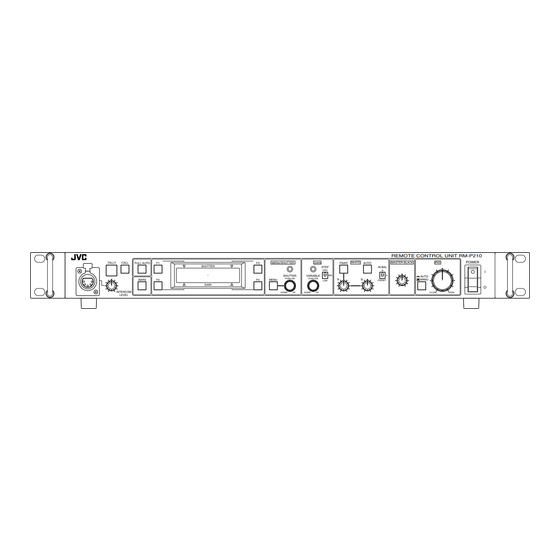
REMOTE CONTROL UNIT RM-P210
POWER
MASTER BLACK
IRIS
W.BAL
B
I
A
AUTO
MANU
PRESET
O
CLOSE
OPEN
SC961002-003-H
Advertisement
Table of Contents

Related Manuals for JVC RM-P210


Summary of Contents for JVC RM-P210
- Page 1 PAINT WHITE SHUTTER STEP HIGH SHUTTER VARIABLE PUSH-ON PUSH-ON MENU GAIN DOWN DOWN INTRODUCTION CONNECTION PREPARATIONS AND MAIN FUNCTIONS CAMERA ADJUSTMENTS MENU OPERATION GENERAL REMOTE CONTROL UNIT RM-P210 POWER AUTO MASTER BLACK IRIS W.BAL AUTO MANU PRESET CLOSE OPEN SC961002-003-H...
- Page 2 IMPORTANT SAFEGUARDS 1. Read all of these instructions. 2. Save these instructions for later use. 3. All warnings on the product and in the operating instructions should be adhered to. 4. Unplug this appliance system from the wall outlet before cleaning. Do not use liquid cleaners or aerosol cleaners. Use a damp cloth for cleaning.
-
Page 3: Table Of Contents
003. Cet appareil numérique de la class B est conforme á la norme NMB-003 du Canada. Changes or modifications not approved by JVC could void the user's authority to operate the equipment. This unit is designed for professional use only. -
Page 4: Introduction
Do not supply power to the RTS terminals at the rear. These terminals are not designed to accept a power supply. To prolong the service life of the RM-P210, do not use it or store it in the following places. -
Page 5: Controls, Connectors And Indicators
When the iris mode is AUTO (when the lamp in the button is not lit up), the auto iris level can be fine adjusted with this knob. REF. “Iris Adjustment” on page 17. INTRODUCTION 8 9 0 REMOTE CONTROL UNIT RM-P210 POWER MASTER BLACK IRIS AUTO W.BAL... - Page 6 “A” or “B”, When this button is pressed, the lamp in it lights up and the RM-P210 outputs the color bar signal. This signal is used during genlock operation. REF. : “Adjustments for Genlock Operation” on page 13.
-
Page 7: Rear Panel
Connect this socket to a camera using the optionally avail- able camera cables. The VC-P110 series camera cables that can be used to con- nect a camera to the RM-P210 are available in four lengths as listed below. VC-P110 : 5 meters... -
Page 8: Connection
Connection of Cameras and Viewfinders ( Viewfinder VF-P550B Camera GY-DV550 KY-D29 KY-D29W KY-27C KY-19 When the RM-P210 is connected to a camera, a local remote controller cannot be connected to the camera. Intercom headset KA-310 LIGHT MODE COUNTER INCOM CARBON DYNAMIC... -
Page 9: Example Of Rm-P210 (Connection Of 2 Units)
SPOT L COMPRESS OPERATE GY-DV550 RM-P210 To power supply RTS unit RM-P210 To power supply If more than three RM-P210 units are connected, the intercom volume level will be reduced. Intercom headset KA-310 MODE INCOM CARBON DYNAMIC Camera cable INCOM... -
Page 10: Camera Setup
CONNECTION CAMERA SETUP Before turning the RM-P210 on, be sure to set up the camera as shown below. GY-DV550 camera IRIS switch “A” or “AUTO” KY-D29/KY-D29W camera IRIS switch “A” or “AUTO” OPERATE switch ON/ST-BY OPERATE/WARNING LIGHT RESET MONITOR SELECT... -
Page 11: Turning The Power On
RM-210 are variable depending on the camera models. When connecting the RM-P210 to the camera, do not connect a local remote controller to the camera. Connect the camera to the RM-P210 using a proper con- nection method. -
Page 12: Preparations And Main Functions Camera Cable Length Setup
CAMERA CABLE LENGTH SETUP Cable length setup is required when a camera is connected to the RM-P210 for the first time or when the camera cable length is changed. The cable length setup value is stored in the memory inside the RM-P210 and is held even after it is turned OFF. -
Page 13: Adjustments For Genlock Operation
Genlocking is required for a system, which uses an SEG (special effects generator) as the main signal source. REF. : “Example of RM-P210 (Connection 2 units) ” on page 9. NOTE The following adjustments can be made more accurately when using a vectorscope and waveform monitor. -
Page 14: Intercom
JVC-authorized service agent. (The modification will then be carried out with charge.) AUX VIDEO INPUT An intercom jack is provided on the front panel of the RM-P210. The volume level of the headset’s earphone can be adjusted using the INTERCOM LEVEL control. -
Page 15: Function Keys
FUNCTION KEYS Up to four of the functions listed at the bottom of this page can be assigned to function keys F1 to F4 so that each function can be switched on or off by pressing the corresponding key. (For the assignment of functions: REF. Items 5H to 5K, “FUNC1” to “FUNC4” in the OPERATION MENU description on page 25.) <Example of factory setting>... -
Page 16: Camera Adjustments Shutter Speed Adjustment
NOTE The variation range is variable depending on the cam- era in use. The shutter speed displayed on the RM-P210 may be slightly different from the actual shutter speed of the camera. The gain is boosted according to the position of the GAIN STEP switch as shown below. -
Page 17: Iris Adjustment
IRIS ADJUSTMENT The camera lens iris can be adjusted from the RM-P210. Iris MODE switch IRIS control REMOTE CONTROL UNIT RM-P210 PAINT WHITE AUTO MASTER BLACK IRIS W.BAL AUTO MANU PRESET CLOSE OPEN IRIS AUTO/MANU button When the lamp in the IRIS AUTO/MANU button is not lit, the iris control is set to AUTO mode, in which the iris level is controlled automatically according to the light intensity. -
Page 18: White Balance Adjustment
WHITE BALANCE ADJUSTMENT Since color temperature varies depending on the light source, the white balance should be ad- justed whenever the main light source illuminating the object being shot changes. AUTO WHITE button REMOTE CONTROL UNIT RM-P210 U/SHUTTER GAIN WHITE... -
Page 19: Menu Operation Flow Of Menus
MENU OPERATION FLOW OF MENUS The menus displayed on the RM-210 are provided in the form shown below. The displayed items and values are variable depending on the connected camera model. (The items and values that are not available with the camera are not displayed.) Category Item 1: GENLOCK... -
Page 20: Menu Setup Method
MENU OPERATION MENU SETUP METHOD Each menu is displayed on the LCD display and can be set up using the MENU button and the control knob. The values set in the "4: PROCESS" and "5: OPERATION" menus can be saved in files A and B. <Example of changing the camera cable length from 20 m to 100 m>... -
Page 21: Genlock Menu
GENLOCK MENU This menu is used to set the camera cable length to the length actually used. ( REF. : “Adjustments for Genlock Operation” on page 13.) Item H PHASE Adjustment of the Horizontal sync phase of genlocking. SC COARSE Coarse adjustment of the color phase of genlocking. -
Page 22: File Menu
MENU OPERATION FILE MENU The values set with the menu and applied to the RM-P210 can be saved in two files named A and B. FULL AUTO SHUTTER 3. FILE BARS GAIN LCD display MENU button 1: GEN LOCK 2: CABLE... -
Page 23: Process Menu
PROCESS MENU This menu sets the functions built into the camera. (Some of the following items cannot be set if a local remote control unit is connected to the camera or depending on the connected camera model.) Item DETAIL ON/OFF setting of the detail enhancement function. OFF : Detail enhancement is deactivated. - Page 24 MENU OPERATION PROCESS MENU (CONTINUED) Item V.RESOLUTION Increases the vertical resolution. NORMAL : Standard value. V.MAX NOTE When the vertical resolution is increased, the sensitivity deterio- rates and bright areas of objects may appear to be colored. GAMMA ON/OFF setting of the gamma curve correction, which determines the reproduction of black.
-
Page 25: Operation Menu
OPERATION MENU This menu sets the functions built into the RM-P210. Item SHUTTER Selects whether the front panel SHUTTER control varies the shutter speed in steps or in fine variation. STEP VARIABLE: Fine, continual variation to be used when shooting V. -
Page 26: Lcd Mode Menu
MENU OPERATION LCD MODE MENU This menu sets up the LCD display. Item CONTRAST Adjusts the contrast of the LCD display. BACKLIGHT Adjusts the setting of the backlight of the LCD display. OFF : Backlight is turned off. : Backlight is turned on. BACK Returns to the previous display. -
Page 27: System Reset Menu
SYSTEM RESET MENU This menu resets the values set by the user to the initial values. FULL AUTO SHUTTER 1/1000 +9dB BARS MENU GAIN LCD display MENU button 6: LCD MODE 7: SYSTEM RESET 7A: SYSTEM RESET 7A: SYSTEM RESET 7A: SYSTEM RESET Initial values The values you've set in the menu items will be reset to the initial values shown on pages 21 to 27. -
Page 28: General Warning Messages
GENERAL WARNING MESSAGES To prevent operational errors, the LCD display shows one of the following warning messages when an erroneous operation is performed. Displayed Message INVALID ENTRY GAIN : LOLUX INVALID ENTRY FULL AUTO : ON INVALID ENTRY GAIN : ALC + EEI INVALID ENTRY W.BAL : FAW INVALID ENTRY... -
Page 29: Functions Available Depending On Camera Models
JVC-authorized service agent for details. *1 Functions as AUTO WHITE with the KY-D29/KY-D29W. *2 Although this function is displayed it is not available. *3 The camera does not have a PVW lamp but the TALLY lamp on the RM-P210 lights in green. GENERAL... -
Page 30: Troubleshooting
Check the camera functions again. Are cables connected properly? Are the power switches of the RM-P210 and camera set to ON? Is the MODE (RM/VTR) switch on the camera adapter set to “RM”? The connected camera does not have the assigned function. -
Page 31: Specifications
AUX VIDEO INPUT Input Signals GENLOCK signal AUX signal Intercom Tally General Input voltage Power consumption Mass Operating temperatures: -5°C to 45°C Accessory REMOTE CONTROL UNIT RM-P210 POWER MENU/SHUTTER GAIN WHITE MASTER BLACK IRIS PAINT AUTO STEP W.BAL HIGH SHUTTER... - Page 32 is a registered trademark owned by Victor Company of Japan, Limited. is a registered trademark in Japan, the U.S.A., the U.K. and many other countries. © 2005 Victor Company of Japan, Limited. Printed in Thailand SC961002-003-H...
Need help?
Do you have a question about the RM-P210 and is the answer not in the manual?
Questions and answers