Table of Contents
Advertisement
Quick Links
Advertisement
Table of Contents

Related Manuals for RadiSys R220

Summary of Contents for RadiSys R220
- Page 1 Setup Guide R220 NETWORK APPLIANCE July 2014...
- Page 2 Added a new chapter on Remote Management. See Chapter 4 for details. © 2014 by RadiSys Corporation. All rights reserved. Radisys is a registered trademarks of RadiSys Corporation. All other trademarks, registered trademarks, service marks, and trade names are the property of their respective owners.
-
Page 3: Table Of Contents
Table of Contents Preface ..............................5 About this manual............................5 What’s new in this release...........................5 Where to get more product information .......................5 Notational conventions ..........................6 Electrostatic discharge ..........................6 Chapter 1: Overview and specifications ..................7 Mechanical characteristics ..........................7 General layout of components........................8 Power supplies ............................9 User panel ..............................11 Safety ................................12... - Page 4 Installing a power supply ...........................38 Installing rack ear covers...........................39 Mounting the R220 into a rack........................40 Chapter 4: Remote Management..................... 47 Remote access to the R220 Network Appliance ..................48 Configuring the R220 Network Appliance....................51 Monitoring the R220 remotely ........................54 Maintenance ..............................57 Appendix A: Safety information......................
-
Page 5: Preface
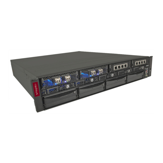
Preface About this manual This manual describes the Radisys R220, a 2U network appliance that is designed for long- term use, flexible configuration, and easy maintenance and upgrading. The product is referred to as the “R220” or “chassis” throughout the remainder of this manual. -
Page 6: Notational Conventions
Preface Notational conventions This manual uses the following conventions BoldText A keyword. ItalicText File, function, and utility names. Screen text and syntax strings. MonoText A command to enter. BoldMonoText ItalicMonoText Variable parameters. Brackets [ ] Command options. Curly braces { } A grouped list of parameters. -
Page 7: Chapter 1: Overview And Specifications
Chapter Overview and specifications The R220 is designed for long-term use while accommodating advances in technology. The server is engineered for flexibility and easy upgrading and maintenance. The chassis and covers are designed to be used with many different configurations. Design highlights include: •... -
Page 8: General Layout Of Components
AC power supply and one DC power supply for illustrative purposes only. This R220 is designed to support 1+1 redundant hot-swappable power supplies. Both bays should be filled with either AC, DC, or PSU blank modules to maintain adequate cooling. -
Page 9: Power Supplies
Overview and specifications Power supplies The R220 is designed to support multiple 80 PLUS® Platinum or Gold efficiency power supplies. Specifications based on the 800W AC power supply and 750W DC power supply are shown in Tables and 3, respectively. - Page 10 The unit shall be installed in a restricted access area in accordance with the authority having jurisdiction. Power consumption The R220 supports many configurations for I/O, storage, and computation. Table 4 documents the power consumption of a maximum configuration where PCIe extenders are used for the front I/O modules, and each front I/O module can consume up to 35 watts.
-
Page 11: User Panel
Overview and specifications User panel The R220 includes a user panel that can be used for monitoring, diagnostics and debugging. The user panel is located in the lower right corner of the front of the chassis, as shown in Figure 2 on page LEDs and buttons The user panel contains various LED lights and two buttons. -
Page 12: Safety
Overview and specifications Diagnostics ports The R220 provides a USB 2.0 port and an RJ45 serial port on the user panel for diagnostics purposes. See Figure Figure 5. Diagnostics ports USB2.0 port RJ-45 serial port Safety Server configurations based on the R220 have been validated against a number of industry standards. -
Page 13: Environment
Overview and specifications Environment The R220 is designed to operate reliably over a broad range of environments, as shown in Table Table 6. Environment specifications Characteristic State Value ° ° ° Temperature (ambient) Operating C to 40 C at a change rate of 30 C per hour °... -
Page 14: Electromagnetic Compatibility
Overview and specifications Electromagnetic compatibility Table 7 Table 8 list the emissions and immunity standards for the R220. Table 7. Emissions standards Characteristic State Standard and test criteria Radiated emissions Operating FCC Part 15, ICES-003 and VCCI Class A EN 55022: 2006,... - Page 15 Overview and specifications Table 8. Immunity standards (continued) Characteristic State Standard and test criteria Conducted susceptibility Operating EN 61000-4-6 AC Power ports: 0.15–80 MHz, 3Vrms DC Power ports: 0.15–80 MHz, 3Vrms Data ports: 0.15–80 MHz, 3Vrms Performance criteria A Voltage dip/interruption Operating EN 61000-4-11 (applies to a range of 200-...
-
Page 16: Chapter 2: Installing The Server
Step 1: Unpack the system unit Remove the R220 from its shipping carton, along with any other materials in the carton. Also unpack any components that will be attached externally to the system unit. If any items are missing, contact your place of purchase. -
Page 17: Step 2: Check The Voltage Range
• If you do not have any options to install, or if you want to set up and run the R220 before installing options, go to Step 4: Connect the cables. - Page 18 Installing the server Figure 6. Ports Location Management port Ethernet Port B Ethernet Port A Serial port USB Port 1 VGA port USB Port 2...
-
Page 19: Step 5. Perform The Check-Out Procedure
3. Follow the instructions in the setup utility interface. Step 7. Finish the installation The R220 hardware is now set up and you are ready to finish the installation by installing the required software and completing the paperwork. The final steps are different for various configurations and applications, but you can use the following checklist as a guide. -
Page 20: Chapter 3: Installing Optional Components
Chapter Installing optional components This chapter provides instructions on installing optional components in the R220. Use the following considerations when installing options: • Before performing any installation procedures, read the information in Appendix A, Safety information, on page ARNING •... -
Page 21: Removing The Cover
The system unit can weigh more than one person can safely lift. Do not attempt to lift it by yourself. Get another person to help you. Perform the following steps to remove the R220 cover. The steps match the numbers shown Figure 1. -
Page 22: Installing Memory Modules
Installing optional components Installing memory modules Refer to R220 Motherboard Manual for information on memory modules compatible with the system. Follow these procedures to add or replace memory modules when the motherboard has already been installed in the chassis. Note: Memory modules are not considered field-replaceable units if they are located under the PCIe assembly and PCIe cables are attached to the PCIe assembly and front I/O modules. - Page 23 Installing optional components Removing memory modules 1. To replace a DIMM, push outward against the outer release lever at the end of the DIMM connector as the inner release lever hides under the middle panel. The DIMM will rise about 0.25 inch. 2.
- Page 24 • Eight DIMMs for each CPU: Populate all DIMM sockets. Figure Important: Populated sockets should contain DIMMs of identical size, type, and speed. The CPUs should be allocated equal total amounts of memory. Figure 10. DIMM socket locations on the R220 motherboard...
- Page 25 Installing optional components General installation procedure 1. Align the centering notches on the DIMM with the keys in the connector. The keys are in the center slot of the connector. 2. Insert the DIMM into the connector and squeeze the DIMM into the connector as shown Figure 11.
-
Page 26: Installing Pcie Cards
Installing PCIe cards PCIe connectivity The R220 motherboard provides direct connectivity from the two CPUs to six 8.0 GT/s PCIe Gen 3 slots located in two riser cards. With both CPUs installed, up to six PCIe slots are available. If only one CPU is installed, only half of the slots are available. - Page 27 Installing optional components Installing PCIe cards To install PCIe cards, follow these steps. Populate the slots closest to the motherboard first to maximize system cooling. 1. Remove the cover as shown in Figure 7 on page 2. Remove the rear PCI assembly, as shown in Figure 8 on page 22, and place it on a grounded surface.
- Page 28 Installing optional components Figure 13. Installing a PCIe card (slots 4, 5 & 6) Riser card L24 PCIe slot 4 - PCIe x16 PCIe slot 5 - PCIe x8 PCIe slot 6 - PCIe x8 PCIe card Figure 14. Installing a PCIe card (slots 1, 2 & 3) Riser card R24 PCIe slot 1 - PCIe x8 PCIe slot 2 - PCIe x16...
-
Page 29: Installing Hard Disk And Solid State Drives
Industrial usage, for example, may subject the system to operating temperatures outside the operating range of standard HDDs or SSDs. Before installing any drive in the R220, be sure that it is rated to operate in the environment where it will be used. - Page 30 Installing optional components Installing or replacing drives in drive bays 0-4 Select any drive carrier in the chassis to add or replace a drive. The R220 system does not need to be powered down for this procedure. Refer to Figure 16 for details.
-
Page 31: Installing And Removing An I/O Module
I/O modules are not hot swappable, and special drive cages must be used to house the drive carriers. Installing and removing an I/O module The basic configuration of the R220 supports up to four I/O modules installed in upper bays. As mentioned in Installing hard disk and solid state drives on page 29, three of the bays (5-7) can be used for additional HDD/SSD with the purchase of optional drive carriers. - Page 32 Installing optional components Figure 18. Installing/removing the I/O module...
-
Page 33: Replacing I/O Modules With Hard Disk Or Solid State Drives
ARNING Be sure to power off the R220 system before you remove or install components in the I/O bays. To install a hard disk drive into one of the I/O bay slots (drive 5, 6, or 7): 1. - Page 34 Installing optional components Figure 20. Inserting the drive carrier into the drive cage...
- Page 35 Drive cage removal Should you ever need to remove a drive cage from an I/O bay slot: 1. Power off the R220 system. 2. Press the ejector latch on the front of the drive carrier to the right. This will release the ejector handle.
-
Page 36: Installing A Blower
Installing optional components Installing a blower The basic configuration of the R220 supports up to four blower units. Blower units are hot- swappable. You can install or remove them when the R220 system is operating. Figure 2 on page 8 shows the blower mounting locations. -
Page 37: Accessing Diagnostic Ports
Installing optional components Accessing diagnostic ports Diagnostic ports are on a sliding tray located in the lower front corner of the system. To access the diagnostics ports: 1. Press and hold the release lever downward. See Figure 2. Pull the tray outward to reveal the diagnostic ports. 3. -
Page 38: Installing A Power Supply
Installing optional components Installing a power supply The basic configuration of the R220 supports two power supplies. Figure 3 on page 8 shows the power supply locations. To install a power supply, follow these steps: 1. Disconnect the power cable that is plugged to the power supply module before installation, if applicable. -
Page 39: Installing Rack Ear Covers
Installing optional components Installing rack ear covers To install a rack ear cover, follow these steps and refer to Figure 1. Insert the rack ear cover bottom “hook” into the rack ear rectangular opening. 2. Pivot the rack ear cover upwards into the rack ear receptacle until it is fully installed. Figure 25. -
Page 40: Mounting The R220 Into A Rack
Installing optional components Mounting the R220 into a rack Three options are available for mounting the R220 into a rack. The options are described in the following sections. Installing rail kits on an EIA 4-post rack (square- or unthreaded round-hole style) Note: Before installation, make sure the distance between the front and rear rack posts is between 475 –... - Page 41 Installing optional components Installing the rail kits into a threaded-hole EIA 4-post rack Before you begin: • Make sure the distance between the front and rear rack posts is between 475 – 700 mm. • Find out the threaded-screw hole size on the rack posts. EIA rails accommodate M5, M6, #10, or #12 screws.
- Page 42 Installing optional components Figure 27. Installing the rail kits into a threaded-hole EIA 4-post rack...
- Page 43 2. Slide the R220 system fully into the rail kits. ARNING The R220 system can weigh more than one person can safely lift. Do not attempt to lift it by yourself. Have another person help you. 3. Install the supplied #10-32 (4x) screws through the rack ears and into the rails.
- Page 44 Installing optional components Installing the rail kits into a Telecom 2-post rack Notes: • Before installation, make sure each rack post is between 120 mm and 270 mm wide. • The Telecom rail kit supports M5/M6, or #10/#12 screws only. Identify the threaded-hole size on the Telecom 2-post rack and use the corresponding screws for installing the rail kit into the rack.
- Page 45 Installing optional components Figure 29. Installing the rail kits into a Telecom 2-post rack...
- Page 46 Installing optional components Installing the system into a Telecom rail kit Perform the following steps to install the R220 system into a Telecom rail kit. The steps match the numbers in Figure 1. Slide the R220 system fully into the rail kits.
-
Page 47: Chapter 4: Remote Management
Alternatively, you can use IPMI commands in utilities such as ipmitool or ipmiutil to access and retrieve management data in the R220. For further information regarding the use of IPMI commands, please download the IPMI Second Generation Specification from www.intel.com. -
Page 48: Remote Access To The R220 Network Appliance
You can access the MegaRAC GUI residing in the R220’s BMC from most of the mainstream browsers. 1. In the address bar of the browser, enter the IP address of the BMC in the R220 system. The default IP address is 192.168.0.250. If you are unable to log in with this address, it is possible that the BMC “configuration address”... - Page 49 Remote Management Figure 32. Sample BMC Network Configuration submenu 3. Change the configuration address to static or dynamic according to what is appropriate for your network. If you set the address to dynamic, the remaining settings in the menu will be determined by the router and will become read-only.
- Page 50 Remote Management Accessing the R220 using the ipmitool utility As an alternative to using the MegaRAC GUI, you can send commands to the R220 using the ipmitool utility. Ipmitool connects to IPMI-enabled devices through an IPMI v1.5 or IPMI v2.0 LAN interface.
-
Page 51: Configuring The R220 Network Appliance
MegaRAC GUI location: Configuration menu, DNS Server Settings page Network settings Some network settings on the R220 may need to be completed, such as the MAC address and IPv4 or IPv6 settings. These settings can be changed in the MegaRAC GUI’s configuration wizard. - Page 52 Alert policies tab In the Alert Policy Tab you can add and configure one or more alert policies to notify multiple users of the R220 Network Appliance. The policies define how the alerts will be processed and where they will be sent.
- Page 53 Remote Management RADIUS authentication Remote Authentication Dial In User Service (RADIUS) can be enabled to authenticate, authorize, and account for users who connect to and use the network. If you enable RADIUS, you must specify the RADIUS port number, the time out, the IP address of the RADIUS server, and the authentication secret for the RADIUS server.
-
Page 54: Monitoring The R220 Remotely
Monitoring the R220 remotely Using the MegaRAC GUI dashboard Viewing the dashboard in the MegaRAC GUI is the easiest way to monitor the R220 remotely and at a high level. Real-time sensor data and event log information is collected from the sensor data records saved in the BMC and displayed in the dashboard. - Page 55 Get Sensor Reading Get Sensor Event Status System event log The R220 system event log is generated by the BMC and can be displayed in the MegaRAC GUI or by issuing IPMI commands. MegaRAC GUI location: Server Health tab, Event Log page...
- Page 56 Product Version Product Serial Number Asset Tag FRU File ID Product Extra You can access R220 FRU information in the MegaRAC GUI or via the management controller or the serial EEPROM using IPMI commands. MegaRAC GUI location: FRU Information tab...
-
Page 57: Maintenance
Restore factory settings When troubleshooting or recovering from a failed firmware update, you may want to restore the entire R220 configuration to its factory settings. There is a simple command for doing this in the MegaRAC GUI. Important: Before restoring all settings to their factory default values, it is recommended that you record your current configuration with screen captures. -
Page 58: Appendix A: Safety Information
• Do not wear jewelry, chains, metal-frame eyeglasses, or metal fasteners for your clothing. Remember: Metal objects are good electrical conductors. • Read the Safety Information document at www.radisys.com/downloads to ensure all precautions are taken to prevent electronic equipment damage resulting from electrostatic discharge. -
Page 59: Rack-Installation Safety
Safety information Rack-installation safety Consider the following when installing this equipment in a rack-mount environment: • Elevated Operating Ambient. If installing in a closed or multiple-unit rack assembly, the operating ambient temperature of the rack environment may be greater than the room ambient temperature. - Page 60 Safety information Inspection checklist 1. Check exterior covers for damage, such as loose, broken, or sharp edges. 2. Power off the equipment and disconnect the power cord. 3. Check the power cord for: a. A third-wire ground connector in good condition. Use a meter to measure third-wire ground continuity for 0.1 ohm or less between the external ground pin and frame ground.
- Page 61 Safety information Electrical equipment safety precautions Observe the following rules when working on electrical equipment. ARNING • Use only approved tools and test equipment. Some hand tools have handles covered with a soft material that does not insulate you when you are working with live electrical currents. •...
- Page 62 Protect against ESD damage by equalizing the charge so the equipment, the part, the work mat, and the person handling the part are all at the same charge. To review ESD safety precautions, read the Safety Information document at www.radisys.com/downloads. ARNING •...
- Page 63 Safety information Grounding requirements Electrical grounding of the equipment is required for operator safety and correct equipment operation. Proper grounding of the electrical outlet can be verified by a certified electrician. Power cord notice For units intended to be operated in DC (-48V to -60V): Use a UL listed and CSA-certified cord set consisting of a minimum 12 AWG two-conductor cord that is a maximum of 15 feet in length.
-
Page 64: Federal Communications Commission (Fcc) Statement
Safety information Federal Communications Commission (FCC) statement This equipment has been tested and found to comply with the limits for a Class A digital device, pursuant to Part 15 of the FCC Rules. These limits are designed to provide reasonable protection against harmful interference when the equipment is operated in a commercial environment. - Page 65 R220RC124AC & R220RC124DC Specification R220RC124AC R220RC124DC Processor and Chipset Intel Xeon E5-2600 Intel Xeon E5-2600 (Family Processors with C600 (Family Processors with C600 Chipset) Chipset Memory Capacity Up to 256GB (with 16GB Up to 256GB (with 16GB DIMMs non-mirrored mode) DIMMs non-mirrored mode) Storage hot-swappable 2.5-inch SAS...
Need help?
Do you have a question about the R220 and is the answer not in the manual?
Questions and answers