Table of Contents
Advertisement
D1 logic unit for barriers and RSB
TECHNICAL MANUAL
PROGRAM VERSION: 06.
MANUAL VERSION: 02.
English language adapted from French.
Automatic Systems s.a.
Head office and factory:
Avenue Mercator 5, 1300 Wavre, Belgium
Tel.: 32-10-23.02.11 Fax: 32-10-23.02.02
Automatic Systems reserves the right to change the characteristics of its products without notice.
Automatic Systems Logic D1 v06-02-en0802.doc ERB-PM
Technical manual
Advertisement
Table of Contents

Related Manuals for Automatic Systems D1

Summary of Contents for Automatic Systems D1
- Page 1 Automatic Systems s.a. Head office and factory: Avenue Mercator 5, 1300 Wavre, Belgium Tel.: 32-10-23.02.11 Fax: 32-10-23.02.02 Automatic Systems reserves the right to change the characteristics of its products without notice. Automatic Systems Logic D1 v06-02-en0802.doc ERB-PM Technical manual...
-
Page 2: Table Of Contents
TABLE OF CONTENTS 1. INTRODUCTION to the D1 Logic unit ..................... 3 1.1. Overview ........................... 3 1.2. Technical specifications ......................4 1.3. Abbreviations used........................4 1.4. References ..........................4 2. The main board AS1200........................5 2.1. Overview ........................... 5 2.2. -
Page 3: Introduction To The D1 Logic Unit
(for example: to activate inputs of a counter). • the contactor board AS1206 permit to use the D1 logic board for a three-phase motor with a three- phase main power supply. •... -
Page 4: Technical Specifications
Barrier closing Out of order I²C bus Inter-Integrated Circuit Bus: internal interconnection collector Input/Output Barrier opening RS232 Serial communication STOP Stop command (stops the movement) References 1.4. Electrical technical file: BLR-D-E01-H03-S05-R00-dte.doc 4/31 Automatic Systems Logic D1 v06-02-en0802.doc ERB-PM Technical manual... -
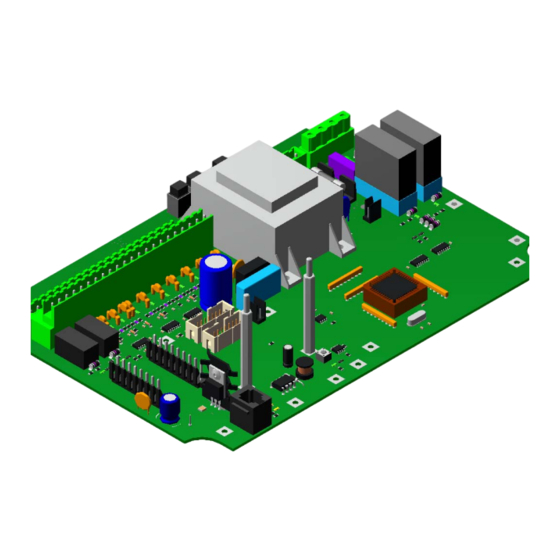
Page 5: The Main Board As1200
The main board AS1200 Overview 2.1. The board AS1200, which is used in all D1 logic units, operates with a single-phase power supply, regardless of whether the motor is single-phased or three-phased. It makes it possible to: manage obstacle commands (opening, closing, stop). - Page 6 X7 (1:7) and X8 (1:8) are the two inputs (24V in negative logic with high impedance, consumption of 10mA) and outputs connectors (relay: potential free contacts; max. 48V, 100mA) making the following external connections possible: 6/31 Automatic Systems Logic D1 v06-02-en0802.doc ERB-PM Technical manual...
- Page 7 X11 (1:10) is intended for the AS Link, to communicate with the console AS1033. * These three STOP commands must be bridged if they are not connected or without SW4-DIP6. 7/31 Automatic Systems Logic D1 v06-02-en0802.doc ERB-PM Technical manual...
- Page 8 220 V D1-D2, then place bridges A2-A3 and B1-B2. 1 / 2 2 / 3 1 / 2 230 V 1 / 2 2 / 3 1 / 2 240 V 8/31 Automatic Systems Logic D1 v06-02-en0802.doc ERB-PM Technical manual...
- Page 9 REL3. LD16 (1:27): green: indicates activation of closing relay REL4. LD17 (1:28): orange: presence of 24V DC. LD18 (1:28): orange: presence of 5V DC. 9/31 Automatic Systems Logic D1 v06-02-en0802.doc ERB-PM Technical manual...
-
Page 10: Operation Mode Parameters
"Step-by-step": only input OVB will wired. One pulse on the input OVB (X8, terminal 3, 23 or 25) reverses the command in progress. No connection can be realised on the input FRB. 10/31 Automatic Systems Logic D1 v06-02-en0802.doc ERB-PM Technical manual... -
Page 11: Programming
16. Arm swing-off STOP command 17. Passage 1 direction 1 BLQO command 18. Passage 1 direction 2 BLQF command 19. Passage 2 direction 1 10. Barrier status 20. Passage 2 direction 2 11/31 Automatic Systems Logic D1 v06-02-en0802.doc ERB-PM Technical manual... -
Page 12: Information Of The Relays
BLQF copies the status of the input BLQF Barrier status The relay chosen with this function engage with the opening command of the barrier and loosen with the closing command. 12/31 Automatic Systems Logic D1 v06-02-en0802.doc ERB-PM Technical manual... -
Page 13: Programming Procedure
Return DIP 1-7 to OFF after introduction of all the parameters. To exit the programming mode, set DIP 8 to OFF. The logic board returns to operation mode. Set the operation mode parameters noted on point 1. 13/31 Automatic Systems Logic D1 v06-02-en0802.doc ERB-PM Technical manual... -
Page 14: Resetting The Parameters By Default
Push on the PGM button SW5 (1:16) and maintain it depressed all along the process. Switch on the power supply of the logic board. The red LED LD2 (1:17) lights on Release the PGM button (1:16) when the red LED LD2 has lit off. 14/31 Automatic Systems Logic D1 v06-02-en0802.doc ERB-PM Technical manual... -
Page 15: Table Of Binary Values For Numbers 0 To 127
95 7 + 5 + 4 + 3 + 2 + 1 111 7 + 6 + 4 + 3 + 2 + 1 127 7 + 6 + 5 + 4 + 3 + 2 + 1 15/31 Automatic Systems Logic D1 v06-02-en0802.doc ERB-PM Technical manual... -
Page 16: Operation
The HIGH address defines the board for sensors 3 and 4 (DP3 and DP4). This address is essential for all functions of the sensors in the programming. The following table indicates the various address for each sensor. 16/31 Automatic Systems Logic D1 v06-02-en0802.doc ERB-PM Technical manual... -
Page 17: 2.5.5.2. Sensor Functions
Two actions may be added following the DPS, (after S, safety stop): maintains the safety Stop (S) and waits for the following command. starts the opening (O) and waits for the following command. 17/31 Automatic Systems Logic D1 v06-02-en0802.doc ERB-PM Technical manual... - Page 18 Variant: If the vehicle does not pass through and leaves the DP2 (DPO), the opening command stops and the barrier closes. In all cases of automatic closing, the DP1 (DPFS) retains its safety stop function during the descending movement. 18/31 Automatic Systems Logic D1 v06-02-en0802.doc ERB-PM Technical manual...
-
Page 19: 2.5.5.3. Vehicle Presence Detector Boards Dp139 And Dp239
If a problem occurs: for example, a breaking of the loop, it flashes every second to indicate the defect. Unconnected loop: lights when power-on, goes off, lights up again for 1 second, goes off again and remains off. 19/31 Automatic Systems Logic D1 v06-02-en0802.doc ERB-PM Technical manual... - Page 20 DP3 (board DP139) or DP3 and DP4 (board DP239) – High Address Sensitivity setting DIP 5 DIP 6 Sensitivity of loop 1 High Medium high Medium low DIP 7 DIP8 Sensitivity of loop 2 High Medium high Medium low 20/31 Automatic Systems Logic D1 v06-02-en0802.doc ERB-PM Technical manual...
-
Page 21: 2.5.5.4. The Board As1225
The lit LED LD2 (7:8) indicates that the entry 2 is activated. Activation of one input corresponds to the closing of the NO contact or opening of the NC contact. 21/31 Automatic Systems Logic D1 v06-02-en0802.doc ERB-PM Technical manual... - Page 22 * This function, which does not provoke any barrier movement, provides information by relays REL1 (1:20) and REL2 (1:21) of the AS1200 board or by relays REL1 (8:5) and REL2 (8:6) of the AS1220 board, according to the programmed choice. 22/31 Automatic Systems Logic D1 v06-02-en0802.doc ERB-PM Technical manual...
-
Page 23: The Interface Board As1220
24V DC 150 mA maxi from the AS1200, two outputs 24V DC (transistor) and two relay NO contacts. The connector X4 (8:3) is the input of the 24 VDC power supply from the AS1048 board and not by the AS1200 board. 23/31 Automatic Systems Logic D1 v06-02-en0802.doc ERB-PM Technical manual... -
Page 24: Barrier Peripherals Connected To The Board As1220
AS1220 board in order to determine the entry and exit directions. Using this mode requires the addition of the double light command relays board AS1049 (see chapter 6). 24/31 Automatic Systems Logic D1 v06-02-en0802.doc ERB-PM Technical manual... -
Page 25: Mode 2: Information Copy-Out
Terminal Ground OVB Entry command (direction A – Reader) Ground OVB Exit command (direction B – Reader) Ground Boom presence switch (FCL) contact NO Ground Lock switch (FCV) contact NF 25/31 Automatic Systems Logic D1 v06-02-en0802.doc ERB-PM Technical manual... -
Page 26: The Switch Sw3
Presence of the boom in the electromechanical tip support Activation of the bolt of the electromechanical tip support Indication of boom lighting Control of electromagnetic tip support REL1 engaged REL2 engaged 26/31 Automatic Systems Logic D1 v06-02-en0802.doc ERB-PM Technical manual... -
Page 27: The Board As1206
U, V and W correspond to the three phases. The terminals C1 and C2 are the common points of the star wiring (see Fig. 10). Motor connection C1-2 STAR TRIANGLE 400V configuration 230V configuration Fig. 10 27/31 Automatic Systems Logic D1 v06-02-en0802.doc ERB-PM Technical manual... - Page 28 Green 240 V TRI TRIANGLE Yellow White Black CONNECTOR C1 C2 X3 AS1206 Blue 380 V TRI 400 V TRI 415 V TRI + Neutral Yellow STAR White Green Black 28/31 Automatic Systems Logic D1 v06-02-en0802.doc ERB-PM Technical manual...
-
Page 29: The Board As1048
Pin 1: Ground and Pin 2: +24 V. The board comprises a fuse F1 T100 mA (11:3) and a fuse F2 T3.15 A (11:4). The red LED (11:5) indicates that power is on. 29/31 Automatic Systems Logic D1 v06-02-en0802.doc ERB-PM Technical manual... -
Page 30: The Board As1049
X4 (12:8) Outputs connector for the contacts from relay REL2 which is used to connect the red bulb (prohibition) in the case of a single light and to connect the red-green light defined on exit in the case of two lights. 30/31 Automatic Systems Logic D1 v06-02-en0802.doc ERB-PM Technical manual... -
Page 31: The Console As1033 (
For specific applications, the board AS1210 is made to control the serial link RS232 (connector X2 (13:1)). It is plugged into the connector X6 (1:6) of the AS1200 board and makes a PC connection possible. 31/31 Automatic Systems Logic D1 v06-02-en0802.doc ERB-PM Technical manual...)
Need help?
Do you have a question about the D1 and is the answer not in the manual?
Questions and answers