Advertisement
Quick Links
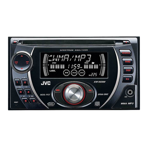
SERVICE MANUAL
6 S ERVICE MANUAL
MA345
2007
KW-XG500J, KW-XG504UI, KW-XG505U,
KW-XG505UN, KW-XG505UH, KW-XG506U,
KW-XG506UN, KW-XG506UH, KW-XG508UF
COPYRIGHT © 2007 Victor Company of Japan, Limited
* Please refer to the mechanism manual (model TN2007-1010
Lead free solder used in the board (material : Sn-Ag-Cu, melting point : 219 Centigrade)
Lead free solder used in the board (material : Sn-Cu, melting point : 230 Centigrade)
1
PRECAUTIONS . . . . . . . . . . . . . . . . . . . . . . . . . . . . . . . . . . . . . . . . . . . . . . . . . . . . . . . . . . . . . . . . . . . . . . . 1-6
2
SPECIFIC SERVICE INSTRUCTIONS . . . . . . . . . . . . . . . . . . . . . . . . . . . . . . . . . . . . . . . . . . . . . . . . . . . . . . 1-9
3
DISASSEMBLY . . . . . . . . . . . . . . . . . . . . . . . . . . . . . . . . . . . . . . . . . . . . . . . . . . . . . . . . . . . . . . . . . . . . . . 1-10
4
ADJUSTMENT . . . . . . . . . . . . . . . . . . . . . . . . . . . . . . . . . . . . . . . . . . . . . . . . . . . . . . . . . . . . . . . . . . . . . . . 1-14
5
TROUBLESHOOTING . . . . . . . . . . . . . . . . . . . . . . . . . . . . . . . . . . . . . . . . . . . . . . . . . . . . . . . . . . . . . . . . . 1-15
All manuals and user guides at all-guides.com
CD RECEIVER
(for KW-XG500)
TABLE OF CONTENTS
COPYRIGHT © 2007 Victor Company of Japan, Limited
(No.MY005
and No.MY005B)) for the CD mechanism.
No.MA345
2007/6
Advertisement

Subscribe to Our Youtube Channel
Related Manuals for JVC KW-XG500J


Summary of Contents for JVC KW-XG500J
-
Page 1: Table Of Contents
All manuals and user guides at all-guides.com SERVICE MANUAL CD RECEIVER MA345 2007 6 S ERVICE MANUAL KW-XG500J, KW-XG504UI, KW-XG505U, KW-XG505UN, KW-XG505UH, KW-XG506U, KW-XG506UN, KW-XG506UH, KW-XG508UF (for KW-XG500) COPYRIGHT © 2007 Victor Company of Japan, Limited * Please refer to the mechanism manual (model TN2007-1010 (No.MY005... - Page 2 All manuals and user guides at all-guides.com SPECIFICATION KW-XG500 AUDIO AMPLIFIER SECTION 20 W RMS × 4 Channels at 4 Ω and [< or =] 1% THD+N Power Output 80 dBA (reference: 1 W into 4 Ω) Signal to Noise Ratio 4 Ω...
- Page 3 All manuals and user guides at all-guides.com KW-XG504 AUDIO AMPLIFIER SECTION Maximum Power Output Front and rear 50 W per channel 19 W per channel into 4 Ω, 40 Hz to 20 000 Hz at no more than 0.8% total har- Continuous Power Output Front and rear (RMS)
- Page 4 All manuals and user guides at all-guides.com KW-XG506/KW-XG505 AUDIO AMPLIFIER SECTION Maximum Power Output Front and rear 50 W per channel 19 W per channel into 4 Ω, 40 Hz to 20 000 Hz at no more than 0.8% total har- Continuous Power Output Front and rear (RMS)
- Page 5 All manuals and user guides at all-guides.com KW-XG508 AUDIO AMPLIFIER SECTION Maximum Power Output Front and rear 50 W per channel 19 W per channel into 4 Ω, 40 Hz to 20 000 Hz at no more than 0.8% total har- Continuous Power Output Front and rear (RMS)
-
Page 6: Precautions
All manuals and user guides at all-guides.com SECTION 1 PRECAUTIONS Safety Precautions Burrs formed during molding may be left over on some parts of the chassis. Therefore, pay attention to such burrs in the case of preforming repair of this system. Please use enough caution not to see the beam directly or touch it in case of an adjustment or operation check. - Page 7 All manuals and user guides at all-guides.com Preventing static electricity Electrostatic discharge (ESD), which occurs when static electricity stored in the body, fabric, etc. is discharged, can destroy the laser diode in the traverse unit (optical pickup). Take care to prevent this when performing repairs. 1.2.1 Grounding to prevent damage by static electricity Static electricity in the work area can destroy the optical pickup (laser diode) in devices such as CD players.
- Page 8 All manuals and user guides at all-guides.com Important for laser products 1.CLASS 1 LASER PRODUCT 5.CAUTION : If safety switches malfunction, the laser is able to function. 2.CAUTION : (For U.S.A.) Visible and/or invisible class II laser radiation 6.CAUTION : Use of controls, adjustments or performance of when open.
-
Page 9: Specific Service Instructions
All manuals and user guides at all-guides.com SECTION 2 SPECIFIC SERVICE INSTRUCTIONS This service manual does not describe SPECIFIC SERVICE INSTRUCTIONS. (No.MA345)1-9... -
Page 10: Disassembly
All manuals and user guides at all-guides.com SECTION 3 DISASSEMBLY MAIN BODY 3.1.1 Removing the FRONT PANEL assembly (See Fig.1) (1) From the bottom side of main body, remove the two screws A attaching the both side of the FRONT PANEL assembly. (2) Disengage two hooks a engaged CHASSIS assembly. - Page 11 All manuals and user guides at all-guides.com 3.1.2 Removing the HEAT SINK (See Fig.2) (1) Remove the five screws B and one screw C attaching the HEAT SINK. Fig.2 3.1.3 Removing the REAR BRACKET (See Fig.3) (1) Remove the seven screws D, two screws E and one screw F attaching the REAR BRACKET.
- Page 12 All manuals and user guides at all-guides.com 3.1.5 Removing the FUNC BOARD assembly (See Fig.5) (1) Remove the one screw H attaching the FUNC BOARD as- CN501 sembly. (2) Disconnect the connecter wire from MAIN BOARD assem- bly connected to connector CN322 of the FUNC BOARD assembly.
- Page 13 All manuals and user guides at all-guides.com 3.1.8 Removing the CD MECHANISM assembly (See Fig.7) (1) Remove the three screws L attaching the CD MECHA- NISM assembly. Fig.7 3.1.9 Removing the SWITCH BOARD assembly (See Fig.8) (1) Remove the volume knob from the front side of the FRONT PANEL assembly.
-
Page 14: Adjustment
(3) Digital tester Load impedance : 20K.(2 Speakers connection) (4) Tracking offset meter Output Level : Line out 2.5V (Vol. MAX) (5) Test Disc JVC :CTS-1000 4.1.3 Standard volume position (6) Extension cable for check Balance and Bass &Treble volume : lndication"0"... -
Page 15: Troubleshooting
All manuals and user guides at all-guides.com SECTION 5 TROUBLESHOOTING 16 PIN CORD DIAGRAM (for KW-XG500) OR/WH Black Green BL/WH Violet Blue Gray WH/BK White Yellow GN/BK Brown Orange VI/BK GY/BK 16 YL MEMORY 8 BK 7 RD 15 OR/WH 13 BR REMOTE 5 BL/WH... - Page 16 All manuals and user guides at all-guides.com 16 PIN CORD DIAGRAM (for KW-XG504, KW-XG505, KW-XG506) Black Green OR/WH Violet BL/WH Blue Gray WH White Yellow WH/BK Brown Orange GN/BK VI/BK GY/BK MEMORY 16 YL 8 BK 7 RD 15 OR/WH 13 BR 3 GN 11 GN/BK...
- Page 17 All manuals and user guides at all-guides.com 16 PIN CORD DIAGRAM (for KW-XG508) Black Green OR/WH Violet Gray BL/WH Blue White Yellow WH/BK Orange Brown GN/BK VI/BK GY/BK NC YL2 OR/WH RD2 BK YL 2 OR/WH GN/BK VI/BK WH/BK GY/BK BL/WH VI/BK GY/BK...
- Page 18 All manuals and user guides at all-guides.com Victor company of Japan, Limited Mobile Entertainment Business Group Mobile Entertainment Category 10-1,1chome,Ohwatari-machi,Maebashi-city,371-8543,Japan (No.MA345) Printed in Japan...
- Page 19 All manuals and user guides at all-guides.com PARTS LIST KW-XG500J,KW-XG504UI,KW-XG505U KW-XG505UN,KW-XG505UH,KW-XG506U KW-XG506UN,KW-XG506UH,KW-XG508UF * All printed circuit boards and its assemblies are not available as service parts. * Please refer to the mechanism manual (model TN2007-1010, No.MY005,MY005B) for the CD mechanism.
- Page 20 All manuals and user guides at all-guides.com Exploded view of general assembly and parts list Block No. Main board S/M : MY005,MY005B KW-XG500J only model : TN2007-1010 Switch board...
- Page 21 All manuals and user guides at all-guides.com Main board G500J only Function board The parts without symbol number are not service.
- Page 22 All manuals and user guides at all-guides.com General Assembly Block No. [M][1][M][M] Symbol No. Part No. Part Name Description Local GE10170-001A TOP CHASSIS LV10864-002A MIDDLE CHASSIS LV10865-002A BOTTOM CHASSIS GE31799-004A REAR BRACKET LV34655-002A HEAT SINK QYSDST2604ZA TAP SCREW M2.6 x 4mm(x3) GE40377-002A SCREW (x4)
- Page 23 All manuals and user guides at all-guides.com Symbol No. Part No. Part Name Description Local GE40218-078A SHEET QYSDST2606ZA TAP SCREW M2.6 x 6mm 500J QAM0991-001 STEELING REMOTE 500J GE40402-001A TOP SHEET 508UF...
- Page 24 All manuals and user guides at all-guides.com Electrical parts list Main board Symbol No. Part No. Part Name Description Local Block No. [0][1] D782 or MA111-X SI DIODE Symbol No. Part No. Part Name Description Local D783 1SS355W-X DIODE D783 or MA111-X...
- Page 25 All manuals and user guides at all-guides.com Symbol No. Part No. Part Name Description Local Symbol No. Part No. Part Name Description Local C186 QEKJ1HM-105Z E CAPACITOR 1uF 50V M C562 QEKJ1CM-476Z E CAPACITOR 47uF 16V M C261 QEKJ1CM-106Z E CAPACITOR 10uF 16V M...
- Page 26 All manuals and user guides at all-guides.com Symbol No. Part No. Part Name Description Local Symbol No. Part No. Part Name Description Local C971 NCB31EK-104X C CAPACITOR 0.1uF 25V K R515 NRSA63J-682X MG RESISTOR 6.8kΩ 1/16W J C991 NDC31HJ-471X C CAPACITOR 470pF 50V J...
- Page 27 All manuals and user guides at all-guides.com Symbol No. Part No. Part Name Description Local Symbol No. Part No. Part Name Description Local R704 NRSA63J-473X MG RESISTOR 47kΩ 1/16W J R851 NRSA63J-103X MG RESISTOR 10kΩ 1/16W J 504UI,505 U,505UN, R705 NRSA63J-473X...
- Page 28 All manuals and user guides at all-guides.com Symbol No. Part No. Part Name Description Local Symbol No. Part No. Part Name Description Local D6104 LHQ974/LM/-X R6300 NRSA63J-821X MG RESISTOR 820Ω 1/16W J D6105 LHQ974/LM/-X R6301 NRSA63J-102X MG RESISTOR 1kΩ...
- Page 29 All manuals and user guides at all-guides.com Symbol No. Part No. Part Name Description Local R325 NRSA63J-0R0X MG RESISTOR 0Ω 1/16W J R331 NRSA63J-821X MG RESISTOR 820Ω 1/16W J R332 NRSA63J-181X MG RESISTOR 180Ω 1/16W J R335 NRSA63J-0R0X MG RESISTOR 0Ω...
- Page 30 All manuals and user guides at all-guides.com Packing materials and accessories parts list Block No. No additional / supplemental order of WARRANTY CARDs are available. A1,A2,A3,A4,A5,A6, A13,A14,A15,A16 The parts without symbol number are not service. 3-12...
- Page 31 All manuals and user guides at all-guides.com Packing and Accessories Block No. [M][3][M][M] Symbol No. Part No. Part Name Description Local GET0462-001A INST BOOK ENG FRE SPA 500J GET0464-001A INST BOOK 504UI GET0463-001A INST BOOK ENG THA 505U,505UH,506U,506UH GET0463-004A INST BOOK ENG INA 505UN,506UN...
- Page 32 All manuals and user guides at all-guides.com SCHEMATIC DIAGRAMS CD RECEIVER KW-XG500J,KW-XG504UI,KW-XG505U KW-XG505UN,KW-XG505UH,KW-XG506U KW-XG506UN,KW-XG506UH,KW-XG508UF CD-ROM No.SML200706 (for KW-XG500) * Please refer to the mechanism manual (model TN2007-1010, No.MY005, MY005B) for the CD mechanism. Lead free solder used in the board (material : Sn-Ag-Cu, melting point : 219 Centigrade)
- Page 33 All manuals and user guides at all-guides.com Safety precaution Burrs formed during molding may be left over on some parts of the chassis. Therefore, pay attention to such burrs in the case of preforming repair of this system. Please use enough caution not to see the beam directly or touch it in case of an adjustment or operation check.
- Page 34 TEL MUTE VOL1 DIMOUT EN601 VOL2 REMOCON CN702 ENCODER STEERING STEERING REMOTE Used for KW-XG500 SO, I/O D6101 to D6127,Q6001,Q6002 DIMOUT SI/SO LIGHTING DISPLAY INT, SCK IC801 SI/SO, BUSCK JVC BUS IC604 JVC BUS REMOCON CH.L/R REMOCON AUX_L/R AUX_L/R AUX IN...
- Page 35 All manuals and user guides at all-guides.com Standard schematic diagrams Main section CN261 QGA2501C1-03 D331 D321 MC2836-X MC2836-X QAU0484-001 R262 R321 R322 R325 RT6N430C-X Q262 Q321 KTD1304-X 1/50 R331 R332 4.7u QNB0190-001 R335 Q331 RT6N430C-X 1/50 R345 Q341 RT6N430C-X R341 R342 IC301 TB2926HQ...
- Page 36 All manuals and user guides at all-guides.com CD section FEED- FEED- R504 R516 C520 8.2k 0.022 FEED+ FEED+ 8.2k CD_8V R515 6.8k R512 7.5k VCC_3.3 R511 CD.L C580 D501 1A3G-T1 4.7/25 R581 R583 R585 R589 CD.R R586 C582 1.5k 8.2k 150p VDD_5V C581...
- Page 37 All manuals and user guides at all-guides.com LCD and Key control section R6003 Q6002 2SA1365/F/-X LCD1 QLD0483-001 CN601 QGB1004J2-24X KEY0 KEY1 KEY2 VOL1 VOL2 DIMOUT LCDCE1 LCDCE2 LCDSCK LCDDATA IC603 IC602 PT6523LQ-L PT6523LQ-L REMOCON S49B S32B S49A S32A S50B S31B S31A S51B S30B...
- Page 38 All manuals and user guides at all-guides.com Printed circuit boards Main board Lead free solder used in the board (material : Sn-Ag-Cu, melting point : 219 Centigrade) Lead free solder used in the board (material : Sn-Cu, melting point : 230 Centigrade) forward side reverse side CN901...
- Page 39 All manuals and user guides at all-guides.com Switch board Lead free solder used in the board (material : Sn-Ag-Cu, melting point : 219 Centigrade) Lead free solder used in the board (material : Sn-Cu, melting point : 230 Centigrade) forward side reverse side D6125 S6300...
- Page 40 All manuals and user guides at all-guides.com < M E M O >...
- Page 41 All manuals and user guides at all-guides.com Victor Company of Japan, Limited Mobile Entertainment Business Group Mobile Entertainment Category 10-1,1chome,Ohwatari-machi,Maebashi-city,Gumma-ken,371-8543,Japan Printed in Japan (No.MA345SCH)
Need help?
Do you have a question about the KW-XG500J and is the answer not in the manual?
Questions and answers