Table of Contents
Advertisement
Quick Links
Advertisement
Table of Contents

Related Manuals for Gigabyte GA-F2A88XM-HD3


Summary of Contents for Gigabyte GA-F2A88XM-HD3
- Page 1 GA-F2A88XM-HD3 User's Manual Rev. 3001 12ME-F288HD3-3001R...
- Page 2 The trademarks mentioned in this manual are legally registered to their respective owners. Disclaimer Information in this manual is protected by copyright laws and is the property of GIGABYTE. No part of this manual may be reproduced, copied, translated, transmitted, or published in any form or by any means without GIGABYTE's prior written permission.
-
Page 3: Table Of Contents
Table of Contents GA-F2A88XM-HD3 Motherboard Layout ................4 GA-F2A88XM-HD3 Motherboard Block Diagram ............5 Chapter 1 Hardware Installation ..................6 Installation Precautions ................... 6 ..................7 Installing the APU .................... 9 Installing the Memory ..................10 Installing an Expansion Card ................. 10 ........... 10 Back Panel Connectors ..................11... -
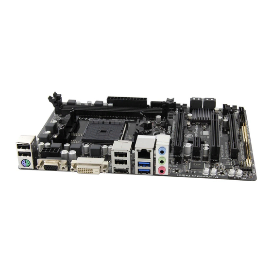
Page 4: Ga-F2A88Xm-Hd3 Motherboard Layout
GA-F2A88XM-HD3 Motherboard Layout KB_MS_USB ATX_12V Socket FM2+ USB_HDMI USB30_LAN SYS_FAN AUDIO GA-F2A88XM-HD3 Realtek ® PCIEX16 GbE LAN PCIEX1 M_BIOS ® Super I/O B_BIOS AMD A88X PCIEX4 CODEC SATA3 1 SPDIF_O CLR_CMOS SATA3 F_AUDIO F_USB2 F_USB1 F_PANEL F_USB30 Box Contents GA-F2A88XM-HD3 motherboard... -
Page 5: Ga-F2A88Xm-Hd3 Motherboard Block Diagram
GA-F2A88XM-HD3 Motherboard Block Diagram 1 PCI Express x16 1 PCI Express x4 Dual Channel Memory PCIe CLK AMD APU HDMI DVI-D D-Sub PCI Express Bus Dual BIOS 1 PCI Express x1 RJ45 Realtek ® PCIe CLK 8 SATA 6Gb/s GbE LAN 4 USB 3.0/2.0... -
Page 6: Chapter 1 Hardware Installation
Chapter 1 Hardware Installation Installation Precautions The motherboard contains numerous delicate electronic circuits and components which can become manual and follow these procedures: Prior to installation, make sure the chassis is suitable for the motherboard. warranty sticker provided by your dealer. These stickers are required for warranty validation. Always remove the AC power by unplugging the power cord from the power outlet before installing or removing the motherboard or other hardware components. - Page 7 * The maximum 64 GB of system memory can be supported using 16 GB or above memory modules. GIGABYTE will update the memory support list on the of cial website when the memory modules are available on the market.
- Page 8 Storage Interface Chipset: 8 x SATA 6Gb/s connectors Support for RAID 0, RAID 1, RAID 5, RAID 10, and JBOD Chipset: 4 USB 3.0/2.0 ports 2 ports on the back panel, 2 ports available through the internal USB header 8 USB 2.0/1.1 ports 4 ports on the back panel, 4 ports available through the internal USB headers Internal 1 x 24-pin ATX main power connector...
-
Page 9: Installing The Apu
Operating Support for Windows 8.1/8/7 32-bit/64-bit System * If you plan to install Windows 8.1, please download the latest drivers from GIGABYTE's website. Support for Windows XP-32bit * To support Windows XP 32-bit, you must install an AMD FM2 Trinity APU. -
Page 10: Installing The Memory
Installing the Memory Read the following guidelines before you begin to install the memory: Make sure that the motherboard supports the memory. It is recommended that memory of the same capacity, brand, speed, and chips be used. Always turn off the computer and unplug the power cord from the power outlet before installing the memory to prevent hardware damage. -
Page 11: Back Panel Connectors
After installing the graphics card driver in the operating system, go to the Browse to Performance\AMD Radeon ™ Dual Graphics and ensure the Enable AMD Radeon Dual Graphics check box is selected. installed. Back Panel Connectors USB 2.0/1.1 Port PS/2 Keyboard/Mouse Port Use this port to connect a PS/2 mouse or keyboard. - Page 12 B. Playback of Blu-ray Disc ™ In order to get better playback quality, when playing the Blu-ray Disc , refer to the recommended system ™ AMD A series processors is enabled. Whether Hardware Acceleration can be enabled for 3D Blu-ray discs is dependent on the RJ-45 LAN Port The Gigabit Ethernet LAN port provides Internet connection at up to 1 Gbps data rate.
-
Page 13: Internal Connectors
Internal Connectors ATX_12V F_USB30 F_USB1/F_USB2 CPU_FAN SYS_FAN SATA3 0/1/2/3/4/5/6/7 F_PANEL Read the following guidelines before connecting external devices: First make sure your devices are compliant with the connectors you wish to connect. Before installing the devices, be sure to turn off the devices and your computer. Unplug the power cord from the power outlet to prevent damage to the devices. - Page 14 1/2) ATX_12V/ATX (2x4 12V Power Connector and 2x12 Main Power Connector) With the use of the power connector, the power supply can supply enough stable power to all the components off and all devices are properly installed. The power connector possesses a foolproof design. Connect the power supply cable to the power connector in the correct orientation.
- Page 15 5) SATA3 0/1/2/3/4/5/6/7 (SATA 6Gb/s Connectors) The SATA connectors conform to SATA 6Gb/s standard and are compatible with SATA 3Gb/s and SATA 1.5Gb/s standard. Each SATA connector supports a single SATA device. The AMD A88X Chipset supports Pin No. SATA3 SATA3 SATA3 least two hard drives.
- Page 16 your chassis front panel audio module to this header. Make sure the wire assignments of the module con- nector match the pin assignments of the motherboard header. Incorrect connection between the module connector and the motherboard header will make the device unable to work or even damage it. For HD Front Panel Audio: For AC'97 Front Panel Audio: Pin No.
- Page 17 10) F_USB1/F_USB2 (USB 2.0/1.1 Headers) optional USB bracket. For purchasing the optional USB bracket, please contact the local dealer. Pin No. Pin No. USB DY+ USB DX- USB DY- No Pin USB DX+ Prior to installing the USB bracket, be sure to turn off your computer and unplug the power cord from the power outlet to prevent damage to the USB bracket.
- Page 18 13) BAT (Battery) in the CMOS when the computer is turned off. Replace the battery when the battery voltage drops to a low level, or the CMOS values may not be accurate or may be lost. You may clear the CMOS values by removing the battery: 1.
-
Page 19: Chapter 2 Bios Setup
To access the BIOS Setup program, press the <Delete> key during the POST when the power is turned on. To upgrade the BIOS, use either the GIGABYTE Q-Flash or @BIOS utility. Q-Flash allows the user to quickly and easily upgrade or back up BIOS without entering the operating system. - Page 20 M.I.T. This section provides information on the BIOS version, CPU base clock, CPU frequency, memory frequency, Whether the system will work stably with the overclock/overvoltage settings you made is dependent on your overall and reduce the useful life of these components. This page is for advanced users only and we recommend you not to M.I.T.
- Page 21 Core Performance Boost (Note 1) Turbo CPB (Note 1) CPB Ratio (Note 1) Cool&Quiet Enabled Lets the AMD Cool'n'Quiet driver dynamically adjust the CPU clock and VID to reduce Disabled Disables this function. SVM Mode C6 Mode Allows you to determine whether to let the CPU enter C6 mode in system halt state. When enabled, the CPU core frequency will be reduced during system halt state to decrease power consumption.
- Page 22 DRAM Timing Selectable Quick and Expert Quick, Expert. When using a non-XMP memory module or is set to Disabled, this item will display as 1.50V. When is set to , this item will display the value based on the SPD data on the XMP memory. The value displayed here is dependent on the CPU being used.
-
Page 23: System Information
Slope PWM CPU Fan Speed Control is set to Manual. Options are: 0.75 PWM value / C ~ 2.50 PWM value / System Fan Speed Control (SYS_FAN Connector) Allows you to determine whether to enable the fan speed control function and adjust the fan speed. Normal Allows the fan to run at different speeds according to the system temperature. -
Page 24: Bios Features
Access Level BIOS settings; the User level only allows you to make changes to certain BIOS settings but not all. Hard Drive BBS Priorities submenu will be presented here. string. Or if you want to install an operating system that supports GPT partitioning such as Windows 7 64-bit, select and devices that support Boot from LAN function, etc. - Page 25 A password is only required for entering the BIOS Setup program. System A password is required for booting the system and for entering the BIOS Setup Allows you to determine whether to display the GIGABYTE Logo at system startup. Disabled skips the CSM Support Never Disables UEFI CSM and supports UEFI BIOS boot process only.
-
Page 26: Peripherals
Administrator Password BIOS Setup. Differing from the user password, the administrator password allows you to make changes to all BIOS settings. User Password Setup. However, the user password only allows you to make changes to certain BIOS settings but not all. To cancel the password, press <Enter>... - Page 27 is set to RAID or AHCI mode of the integrated SATA3 4~SATA3 5 connectors. HD Audio Azalia Device If you wish to install a 3rd party add-in audio card instead of using the onboard audio, set this item to Disabled. If you wish to install a 3rd party add-in network card instead of using the onboard LAN, set this item to Disabled.
-
Page 28: Power Management
UMA Frame Buffer Size Integrated Graphics is set to Force amount of system memory allocated solely for the onboard graphics controller. MS-DOS, for example, will ATA Port Information This section provides information on the device connected to each SATA port controlled by AMD Chipset. parallel port. - Page 29 Resume by Alarm If enabled, set the date and time as following: Wake up hour/minute/second: Set the time at which the system will be powered on automatically. Note: When using this function, avoid inadequate shutdown from the operating system or removal of the AC power, or the settings may not be effective.
-
Page 30: Save & Exit
Save & Exit Save & Exit Setup Press <Enter> on this item and select Yes. This saves the changes to the CMOS and exits the BIOS Setup program. Select No or press <Esc> to return to the BIOS Setup Main Menu. Exit Without Saving Press <Enter>... -
Page 31: Chapter 3 Appendix
Chapter 3 Appendix Before you begin Motherboard driver disk. A. Installing SATA hard drive(s) in your computer Attach one end of the SATA signal cable to the rear of the SATA hard drive and the other end to available SATA port on the motherboard. - Page 32 rcadm -C -r0 -d 0 1 -s 40000 ("C"= s x0000 rcadm -C -r5 -d 1 2 3 4 -s 75000 ("C"= After you create the array, you can enter the "rcadm -M -qa" commands to see the array information. In addition to the CONTROLLER LIST and DISK LIST information, you will see ARRAY LIST information displayed on the screen, too.
- Page 33 With the correct BIOS settings, you are ready to install the operating system. A. Installing Windows 8/7 Step 1: You need to install the SATA RAID/AHCI driver during the OS installation. Use an alternative system to copy Hw8_A88 folder under BootDrv in the driver disk. Step 2: Boot from the Windows 8 setup disk and perform standard OS installation steps.
-
Page 34: Drivers Installation
Drivers Installation After installing the operating system, insert the motherboard driver disk into your optical drive. Click on the message "Tap to choose what happens with this disc" on the top-right corner of the screen and select "Run Run After inserting the driver disk, "Xpress Install" will automatically scan your system and then list all the drivers that are recommended to install. -
Page 35: Regulatory Statements
Contravention will be prosecuted. We believe that the information contained herein was accurate in all respects at the time of printing. GIGABYTE cannot, however, assume any responsibility for errors or omissions in this text. Also note that the information in this document is subject to change without notice and should not be construed as a commitment by GIGABYTE. -
Page 36: Contact Us
Address: No.6, Bao Chiang Road, Hsin-Tien Dist., New Taipei City 231,Taiwan TEL: +886-2-8912-4000, FAX: +886-2-8912-4005 You may go to the GIGABYTE website, select your language in the language list on the top right corner of the website. GIGABYTE Global Service System question, please link to: http://ggts.gigabyte.com.tw...
Need help?
Do you have a question about the GA-F2A88XM-HD3 and is the answer not in the manual?
Questions and answers