
Related Manuals for Lars Thrane LT-3100


Summary of Contents for Lars Thrane LT-3100
- Page 1 User & Installation Manual LT-3100 Satellite Communications System Document Number: 95-100765 Rev 1.06 Release date: January 2022 Copyright © Lars Thrane A/S Denmark ALL RIGHTS RESERVED...
- Page 3 Manuals issued by Lars Thrane A/S are periodically revised and updated. Anyone relying on this information should acquire the most current version e.g. from Lars Thrane A/S. Lars Thrane A/S is not responsible for the content or accuracy of any translations or reproductions, in whole or in part, of this manual from any other source.
- Page 4 Failure to comply with these precautions or with specific warnings elsewhere in this manual violates safety standards of design, manufacture and intended use of the equipment. Lars Thrane A/S assumes no liability for the customer's failure to comply with these requirements. Instructions for the Operator...
- Page 5 - Consult the dealer or an experienced radio/TV technician for help. This product does not contain any user-serviceable parts. Repairs should only be made by an authorized Lars Thrane A/S service center. Unauthorized repairs or modifications could result in permanent damage to the equipment and void your warranty and your authority to operate this device under Part 15 regulations.
- Page 6 About this manual Intended readers This is a User & Installation Manual for LT-3100 Satellite Communications System, or LT-3100 system. The manual is primarily intended for installers and service personnel. Personnel installing or servicing the system should be professionals with technical expertise, properly trained, and likewise authorized.
- Page 7 Table 1: Software Versions IMPORTANT: The latest software released by Lars Thrane A/S must always be used for new installations of the LT-3100 System and should be updated to ensure the best possible performance of the system and services. NOTE: The latest LT-3100 Software and Release Notes can always be downloaded from the Lars Thrane A/S website.
- Page 8 LT-3100 User & Installation Manual Rev. 1.06 Introduction Record of Revisions Rev. Description Release Date Initials 1.00 Original document. January 12, 2018 1.01 Editorial corrections. January 17, 2018 As a result of the certification completed, the following sections are updated: 1.02...
-
Page 9: Table Of Contents
LT-3100 User & Installation Manual Rev. 1.06 Introduction Table of Contents Introduction ..............................1 Application and Limitations..........................2 Unpacking (in-the-box) ............................. 3 Inspection ..............................3 Accessories ................................ 4 Mounts ................................4 Cable and connectors ........................... 4 System Overview .............................. 5 Installation and Mounting .......................... - Page 10 LT-3100 User & Installation Manual Rev. 1.06 Introduction Software Update ............................53 System Services ............................... 54 Voice call ..............................54 SMS ................................60 External SIP Phones ............................ 65 Analogue Phone Adapter..........................67 Data (Modem Data, SMS and SBD) ......................68 Tracking ...............................
- Page 11 LT-3100 User & Installation Manual Rev. 1.06 Introduction App. F - GNSS Receiver Integrity States ....................140 App. G - Specifications ..........................145 App. H - Outline Drawing: LT-3110 Control Unit..................146 App. I - Outline Drawing: Bracket Mount, Control Unit ................147 App.
-
Page 12: Introduction
Thrane A/S. The LT-3100 system is designed for the professional market (deep sea, fishing, and workboats), but can be used for the leisure market as well. The LT-3100 system meets all standards and certification requirements needed for worldwide maritime satellite communication equipment. -
Page 13: Application And Limitations
LT-3100 User & Installation Manual Rev. 1.06 Application and Limitations Application and Limitations • The LT-3100 system shall be installed according to manufacturer’s User & Installation Manual. • The LT-3100 system includes an integrated Global Navigation Satellite System (GNSS) receiver for position fixing. -
Page 14: Unpacking (In-The-Box)
WARNING: To avoid electric shock, do not apply power to the LT-3100 system components if there is any sign of shipping damage to any part of a unit or the outer cover. Read the Safety Instructions at the front of this manual before installing or operating the system. -
Page 15: Accessories
N connector. NOTE: For further details on the cable and connectors, please contact Lars Thrane A/S. A coaxial cable up to a length of 500 meters can be used for connecting the LT-3110 Control Unit and the LT-3130 Antenna Unit. Details about the coaxial cable, specification, and cable lengths, are described in LT-3130 Antenna Unit on page 11. -
Page 16: System Overview
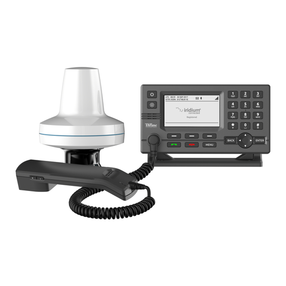
System Overview The LT-3100 Satellite Communications System is a standalone communication product, which is using the Iridium® satellite constellation. The LT-3100 system is working on the new Iridium® NEXT satellites. An overview of the LT-3100 system is illustrated in Figure 1. -
Page 17: Installation And Mounting
LT-3100 User & Installation Manual Rev. 1.06 Installation and Mounting Installation and Mounting LT-3110 Control Unit The LT-3110 Control Unit is the master unit in the system, supporting all external interfaces and the operational user interface. The LT-3110 Control Unit is designed for indoor mounting. Check the specifications in App. - Page 18 (P/N: 91-100771) or Flush Mount, Control Unit (P/N: 91-100772) - illustrated in Figure 4 and Figure 5. The Flush Mount, Control Unit is not included in the LT-3100 Satellite Communications System – Basic (P/N: 90-101142) and must be ordered separately.
- Page 19 LT-3100 User & Installation Manual Rev. 1.06 Installation and Mounting The Bracket Mount and Flush Mount for the LT-3110 Control Unit are illustrated in Figure 4 and Figure 5. Figure 4: Bracket Mount, Control Unit. Figure 5: Flush Mount, Control Unit.
-
Page 20: Lt-3120 Handset
Installation and Mounting LT-3120 Handset The LT-3120 Handset is the primary voice interface for the LT-3100 system. The LT-3120 Handset must be connected on the front of the LT-3110 Control Unit. The connector is illustrated in Figure 2 on page 6. -
Page 21: Lt-3121 Cradle
LT-3100 User & Installation Manual Rev. 1.06 Installation and Mounting LT-3121 Cradle The LT-3121 Cradle is used together with the LT-3120 Handset. The LT-3121 Cradle should be mounted next to the LT-3110 Control Unit, supporting the LT-3120 Handset. The LT-3121 Cradle specifications are available in App. -
Page 22: Lt-3130 Antenna Unit
Mount the unit on a rigid structure with a minimum of exposure to vibration and shock • Mount the unit using either the Bracket Mount or Pole Mount provided by Lars Thrane A/S • Mount the unit outdoor with an ambient temperature between -40°C to +55°C (-40°F to +131°F) •... - Page 23 LT-3100 User & Installation Manual Rev. 1.06 Installation and Mounting To avoid breaking the LT-3130 Antenna Unit N-connector (female), it is important not to use tooling when connecting and fastening the coaxial cable N-connector (male) to the antenna unit. The coaxial cable N- connector thread nut must be fastened by hand only.
- Page 24 LT-3100 User & Installation Manual Rev. 1.06 Installation and Mounting The LT-3130 Antenna Unit has a hazard warning label attached to the radome as illustrated in Figure 12 Figure 12: LT-3130 Antenna Unit (incl. warning label) WARNING: The safety distance from the LT-3130 Antenna Unit, is 0.1 m (0.3 ft), in order to comply with the regional regulations.
- Page 25 LT-3100 User & Installation Manual Rev. 1.06 Installation and Mounting The LT-3130 Antenna Unit must be installed outside the main beam of the radar. Typically, this is in the order of 10 degrees. To avoid near field antenna coupling, a minimum distance of 2.5 m (6 ft) between the radar antenna and the LT-3130 Antenna Unit must be obeyed.
- Page 26 LT-3100 User & Installation Manual Rev. 1.06 Installation and Mounting The LT-3130 Antenna Unit must be mounted minimum 1 m from MF-HF, VHF, and UHF antennas. Figure 14: LT-3130 Antenna Unit – Separation to MF-HF, VHF, and UHF antennas. NOTE: The LT-3130 Antenna Unit must be installed with a 360°...
- Page 27 LT-3100 User & Installation Manual Rev. 1.06 Installation and Mounting The LT-3130 Antenna Unit must be mounted with free line of sight to the Iridium satellites for best possible performance. The best location will typically be at the top of the lantern mast, where there are no obstructions blocking the Iridium satellite link.
- Page 28 Iridium satellites. IMPORTANT: For best possible performance of the LT-3100 system, the LT-3130 Antenna Unit must have free line of sight to the Iridium satellites as illustrated in Figure 16 and in Figure 17 (clear view angle below the horizontal plan).
- Page 29 Installation and Mounting Coexisting with Inmarsat L-band It is possible to install the LT-3100 system onboard a vessel that already has Inmarsat C equipment installed. It is important to note that the LT-3130 Antenna Unit must be mounted below the Inmarsat C antenna with a minimum distance of 1 m and below an angle of minimum 15°...
-
Page 30: Bracket Mount (1.5" To 2.5" Pipe), Antenna Unit
100989) and coaxial cable N connector from corrosion over time. The Cable Hose can be ordered separately from Lars Thrane A/S on the following P/N: 91-102470 Cable Hose (standalone). The Cable Hose, incl. installation steps, is more detailed illustrated in document: 43-100773 Bracket Mount Assembly (Illustrations). - Page 31 LT-3100 User & Installation Manual Rev. 1.06 Installation and Mounting The Bracket Mount (1.5” to 2.5” pipe), Antenna Unit installation options are illustrated in Figure 19 to Figure 24. Figure 20: Bracket Mount (1.5” to 2.5” Figure 19: Bracket Mount (1.5” to 2.5” pipe), pipe), Antenna Unit –...
- Page 32 LT-3100 User & Installation Manual Rev. 1.06 Installation and Mounting Figure 21: Bracket Mount (1.5” to 2.5” pipe), Antenna Unit – horizontal pipe mount. The Bracket Mount (1.5” to 2.5” pipe), Antenna Unit can support pipes in the interval 1.5” to 2.5”. The torques are specified in Figure 22.
- Page 33 LT-3100 User & Installation Manual Rev. 1.06 Installation and Mounting To avoid corrosion issues when using the Bracket Mount (1.5” to 2.5” pipe), Antenna Unit - it is recommended to use the cable hose as illustrated in Figure 23 and in Figure 24. The cable hose consists of a UV resistant silicone pipe and an aluminum anodized thread block, which can be fastened to the LT-3130 Antenna Unit providing protection to the coaxial cable N connector and surroundings.
-
Page 34: Pole Mount (1.5" Pipe, 38.8 Mm), Antenna Unit
LT-3100 User & Installation Manual Rev. 1.06 Installation and Mounting Pole Mount (1.5” pipe, 38.8 mm), Antenna Unit The Pole Mount (1.5” pipe), Antenna Unit is illustrated in Figure 25 to Figure 27. Figure 25: Pole Mount (1.5” pipe), Antenna Unit. - Page 35 LT-3100 User & Installation Manual Rev. 1.06 Installation and Mounting Figure 26: Pole Mount (1.5” pipe), Figure 27: Pole Mount (1.5” pipe), Antenna Unit. Antenna Unit. NOTE: The Pole Mount (1.5” pipe), Antenna Unit only supports a 1.5” pipe. The pinot screws (antenna and pole lock) torques are specified in Figure 26 and Figure 27.
-
Page 36: Pole Mount (2.0" Pipe, 53.0 Mm), Antenna Unit
LT-3100 User & Installation Manual Rev. 1.06 Installation and Mounting Pole Mount (2.0” pipe, 53.0 mm), Antenna Unit The Pole Mount (2.0” pipe, Ø53.0 mm), Antenna Unit is illustrated in Figure 28 to Figure 30. Figure 28: Pole Mount (2.0” pipe, Ø53.0 mm), Antenna Unit. - Page 37 LT-3100 User & Installation Manual Rev. 1.06 Installation and Mounting Figure 29: Pole Mount (2.0” pipe, Ø53.0 Figure 30: Pole Mount (2.0” pipe, Ø53.0 mm), mm), Antenna Unit. Antenna Unit. NOTE: The Pole Mount (2.0” pipe, Ø53.0mm), Antenna Unit only supports a 2.0” pipe. The pinot screws (antenna and pole lock) torques are specified in Figure 29 and Figure 30.
-
Page 38: Interfaces
Figure 31: LT-3110 Control Unit (back view) DC input (PWR) The LT-3100 system is designed to be used on 12 VDC and 24 VDC power buses (nominal). External DC power to the LT-3100 system is provided by connecting the proprietary 91-102118 Power Cable, 3m - delivered by Lars Thrane A/S. - Page 39 LT-3100 User & Installation Manual Rev. 1.06 Interfaces Chassis ground The chassis ground connector is placed on the back side of the LT-3110 Control Unit and marked with ‘GNDC’, see Figure 31 on page 27. Lars Thrane A/S www.thrane.eu Page 28 of 155...
- Page 40 Interfaces SIM card (SIM) The LT-3100 system requires a SIM card to be operated with the Iridium® satellite services. The Iridium® SIM card must be bought from one of the official Iridium® Service Providers. A list of Iridium® Service Providers can be found at the Iridium® website: https://www.iridium.com (select ‘Services’, and hereafter ‘Voice’).
- Page 41 If the user decides to activate the SIM lock function from the UI display, then the PIN code is required next time the LT-3100 system is powered up. Change of the SIM card PIN code can only be performed, if the PIN lock is enabled.
- Page 42 Figure 34: AUX cable pin out NOTE: Use only the 91-100768 Auxiliary Cable, 3m delivered by Lars Thrane A/S for connecting to the AUX connector on the backside of the LT-3110 Control Unit. The Auxiliary Cable, 3m is an accessory part and must be acquired separately.
- Page 43 LT-3100 User & Installation Manual Rev. 1.06 Interfaces RS-422 Circuit Diagram (LT-3110 CU – Aux Connector) Figure 35 shows the RS-422 circuit diagram used for the LT-3110 Control Unit (Aux connector). Figure 35: RS-422 Circuit Diagram for the LT-3110 CU Interface Drive Capability as a Talker and Listener •...
- Page 44 Interfaces External Output (External Ringer) The LT-3100 system support connection of an external speaker for incoming call notifications. Connection of the external speaker must be completed as illustrated in Figure 36, incl. a relay. The maximum voltage and current for the relay are illustrated in the figure. Aux Cable Pin 2 External Output (Pin2) and External Output (Pin1) designation and wire colors are listed in Table 3 on page 31.
- Page 45 LT-3100 User & Installation Manual Rev. 1.06 Interfaces N Connector (ANT) The LT-3110 Control Unit has a N Connector (male) for the interface to the LT-3130 Antenna Unit. The N Connector interface is providing data communication and power to the antenna unit over a coaxial cable.
- Page 46 Interfaces Bluetooth The LT-3110 Control Unit has built in Bluetooth 4.0 with integrated antenna providing wireless communication between Bluetooth capable devices and the LT-3100 system. Max Power: RF Tx Power 10 dBm NOTE: The Bluetooth interface and pairing is described in Bluetooth on page 74.
-
Page 47: Lt-3130 Antenna Unit
Lars Thrane A/S has calculated the maximum allowed cable lengths with two coaxial cables as illustrated in Table 6. The two coaxial cables are FF195LSFROH (~RG-58) and FF400LSFROH (~RG-214/LMR400). - Page 48 FF400LSFROH), then verify that the RF and DC coaxial cable requirements (Table 4 and Table 5) are respected and calculate the maximum cable length as a function of the input voltage and the total DC resistance. Contact Lars Thrane A/S to get assistance on selection and acceptance of a specific coaxial cable.
-
Page 49: Power Consumption
LT-3100 User & Installation Manual Rev. 1.06 Power Consumption Power Consumption The LT-3100 system is powered from 12 VDC or 24 VDC power source. This section will provide power consumption details for maximum power consumption and typical average power consumption. Maximum The LT-3100 system maximum power consumption is listed in Table 8 and in Table 9. -
Page 50: Dc Isolation Resistance And Chassis Ground
DC Isolation Resistance and Chassis Ground DC Isolation Resistance and Chassis Ground The LT-3100 system must be installed properly with respect to DC isolation resistance and chassis ground. Wrong installations can lead to DC isolation issues (low Ohm meter measuring) on board the vessel and equipment damages. - Page 51 MΩ. VDC (-) and VDC (+) is respectfully the N connector thread and the N connector center conductor. Figure 39 is illustrating the LT-3100 system consisting of LT-3110 Control Unit, LT-3130 Antenna Unit, and the coaxial cable connecting these two units.
-
Page 52: Galvanic Isolated Power Supply
Galvanic Isolated Power Supply Galvanic Isolated Power Supply Use an IEC 60945 approved AC/DC or DC/DC galvanic isolated power supply for the LT-3100 system. The galvanic isolated power supply must be used to protect the LT-3100. AC/DC Galvanic Isolated Power Supply Connection of an AC/DC galvanic isolated power supply is illustrated in Figure 40. -
Page 53: User Interface (Ui)
User Interface (UI) User Interface (UI) The LT-3100 system is controlled from the LT-3110 Control Unit, which is the interface for operating and configuring the system. The control unit has a 4.3” TFT-LCD display, supporting day and night modes. The layout of the display and buttons is illustrated in Figure 42. -
Page 54: Display
LT-3100 User & Installation Manual Rev. 1.06 User Interface (UI) respectfully. The arrow buttons can be used to change brightness level if the brightness button has activated the brightness bar. • Numeric Keypad buttons: The numeric keypad buttons, the '*' button, and the '+' button can be used for entering digits, letters and special characters. - Page 55 Network Status – Slot 1 The LT-3100 system has no satellite signal and is not registered on the Iridium® Network. The LT-3100 system has satellite signal = 0 and is registered on the Iridium®...
- Page 56 LT-3100 User & Installation Manual Rev. 1.06 User Interface (UI) Iridium Service – Slot 2 Active voice call or off-hook mode. An external (SIP) phone is in an active voice call. Voice service unavailable due to an unspecified error There is an active data connection.
- Page 57 LT-3100 User & Installation Manual Rev. 1.06 User Interface (UI) Input Mode – Slot 5 The numeric keypad can be used to enter a phone number or numeric number. The numeric keypad can be used to enter text. The first letter of a sentence will be in upper case.
-
Page 58: Menu System
User Interface (UI) Menu System The LT-3100 system’s main menu is accessed by pressing the MENU button on the keypad. The user will be presented with a layout as illustrated in Figure 45. Figure 45: LT-3110 Control Unit - UI display (main menu). - Page 59 LT-3100 User & Installation Manual Rev. 1.06 User Interface (UI) The main menu is represented by three submenus: Phone, Settings, and System. The three submenus are listed in Table 17. Phone submenu: MENU -> Phone Figure 46: Phone submenu Settings submenu: MENU ->...
-
Page 60: Activating The System
The Lars Thrane A/S certified partners have completed technical training and will be able to assist you with all the questions you might have to the product or service. The Lars Thrane A/S certified partners are listed on the company’s website: https://www.thrane.eu The following is required for activating the LT-3100 system: •... -
Page 61: Acquire A Sim Card
Acquire a SIM Card An Iridium SIM card must be used for activating a LT-3100 system. The SIM card is described and illustrated in SIM card (SIM) on page 29. The SIM card may be acquired directly from your Lars Thrane A/S certified partner. -
Page 62: Who's My Service Provider
MSISDN (Mobile Subscriber ISDN number) NOTE: The Iridium Service Provider (SP) must be contacted for any changes to the provisioning. ‘Who’s My Service Provider’ will inform you where your LT-3100 system is provisioned. Lars Thrane A/S www.thrane.eu Page 51 of 155... -
Page 63: Change Of Hardware And Software
Change of Hardware and Software Change of Hardware and Software Change of Hardware This section will provide some guidance on replacing system units and what the user of the LT-3100 system should be aware of, see Table 18. Change of Hardware... -
Page 64: Software Update
Change of Hardware and Software Software Update The LT-3100 system must be software updated by using the web server, see Maintenance, Software update on page 130. Accessing the web server is described in Accessing the built-in web server on page 101. The software update procedure will automatically update all system units connected to the LT-3110 Control Unit. -
Page 65: System Services
Call History placed in the Phone submenu (MENU -> Phone -> Call History), see Phone on page 77. NOTE: Verify that the LT-3100 system is ready to make or receive a voice call. Check the network registration status, as illustrated in on page 44 (Network Status - Slot 1), which is Table 10 presenting the signal level and network registration status. - Page 66 LT-3100 User & Installation Manual Rev. 1.06 System Services The voice call (on-hook and off-hook mode) will be described and illustrated on the following pages. On-hook mode: In on-hook mode the user can either type in the number directly in the display or use the Contacts or Call History to identify the number to be called while the handset is still placed in the cradle.
- Page 67 LT-3100 User & Installation Manual Rev. 1.06 System Services The LT-3100 system has established a voice call to ‘Thrane Test’ (Duration: 00:03). Figure 54: Outgoing Voice Call, on-hook mode (4 of 5) The voice call can be terminated by placing the...
- Page 68 Figure 58: Outgoing Voice Call, off-hook mode (3 of 3) NOTE: The LT-3100 system will provide the user with information, while connecting and throughout the voice call. In case of problems with the satellite network or connection to the called party (far-end), the user will be informed through a voice prompt, and by status cause codes, that will be presented on the display (e.g.
- Page 69 System Services Mobile Terminating (MT) - Incoming The LT-3100 system supports receiving an incoming voice call. The calling party must use the LT- system MSISDN number. The LT-3100 system will check the calling number up against the Contacts entries, if a match exists, the name of the contact will be showed for the incoming voice call.
- Page 70 NOTE: An incoming missed voice call is illustrated in the above figures. By highlighting the missed call in the Call History and press the off-hook button, the LT-3100 system will start establishing a voice call to the party. Lars Thrane A/S www.thrane.eu...
-
Page 71: Sms
Sending an Email from the LT-3100 system is handled similar to sending a SMS,To insert the Email address in the ‘To:’ field use the # key to toggle between numbers and letters. If sending an Email to the LT-3100 system, then leave the Subject-field empty. Please note that all text larger than an SMS (160 characters) is truncated and that the length of the Email address + one character is deducted from the payload text. - Page 72 Sending SMS To send a SMS, the user of the LT-3100 system must access the Phone submenu (MENU -> Phone -> SMS). In the SMS window all sent and received SMS are visible. In Figure 66 the SMS window is illustrated with ‘No Messages’.
- Page 73 Press the soft key ‘Send’ when the destination address and body text have been completed. The SMS service will indicate the transmitting status, which will change from ‘Sending’ to ‘Sent’ when the SMS has successfully been sent from the LT-3100 system, see Figure 71 and Figure 72. Write the SMS text.
- Page 74 LT-3100 User & Installation Manual Rev. 1.06 System Services NOTE: If sending the SMS is failing (the SMS window will indicate ‘Failed’), then a ‘Resend’ soft key will be available for the user to make another try. A successful SMS sending will be indicated by ‘Sent’...
- Page 75 LT-3100 User & Installation Manual Rev. 1.06 System Services NOTE: The LT-3100 system is handling SMS conversions, which is grouped based on the recipient's address. NOTE: SMS and Email can also be sent from the Web Server, see Web server, Messages on page 103.
-
Page 76: External Sip Phones
System Services External SIP Phones The LT-3100 system is supporting connection of external SIP phones, up to 8 external SIP phones. The configuration of the SIP phones must be completed via the web server, see Telephony on page 115. Figure 76 is illustrating the connection of the external SIP phones. - Page 77 ‘lines’ the voice call is locked to this user. The LT-3100 system is supporting local calling between the SIP phones and the LT-3120 Handset. The number plan is illustrated in Table 20. The Caller ID is defined by the user, when configuring the SIP phones.
-
Page 78: Analogue Phone Adapter
Step 1: Connect the LT-3100 system, Analogue Phone Adapter, and PC using a passive switch Step 2: Login to the LT-3100 system web server. The IP address can be read from the display (MENU -> System -> Network: IP address) Step 3: Configure the LT-3100 system to ‘DHCP Server’... -
Page 79: Data (Modem Data, Sms And Sbd)
System Services Data (Modem Data, SMS and SBD) The LT-3100 System is supporting a serial asynchronous automatic dialing and control interface (V250). The interface makes it possible for external equipment (DTE) to use the Iridium 2.4 kbps Modem Data (Direct Internet, RUDICS and SBD) service. - Page 80 Figure 82: Modem Data service terminate By pressing the soft key ‘Terminate Data’ the user of the LT-3100 system can manually terminate the Modem Data connection. The user of the LT-3100 system must confirm the termination of the Modem Data connection by pressing the soft key ‘Yes’.
- Page 81 LT-3100 User & Installation Manual Rev. 1.06 System Services Installation of the Serial Port Redirector (virtual COM port) and Windows Dial-up Networking is further described in the following Lars Thrane A/S LT-3100 Tech Notes, which can be downloaded from our company website: •...
-
Page 82: Tracking
Table 23: Tracking Transport Types & Report Format If periodic tracking reports have been configured by the user of the LT-3100 system in the web server, then a tracking symbol will be shown in the status bar of the LT-3110 Control Unit display. Also, this is to inform the user that tracking reports will be sent periodically. - Page 83 Figure 85: Tracking (Last Report) NOTE: The LT-3100 system support configuration of periodic tracking reports using different transport types and formats. The periodic tracking reports must be configured using the web server, see Configuration - Tracking in Tracking on page 117 Lars Thrane A/S www.thrane.eu...
- Page 84 Figure 84 on page 72. The LT-3100 system will preformat a position report using the SMS functionality and layout, where the user optionally can select between a regular subscriber number and an Email address. Use the hash ‘#’ key to toggle between numbers and letters in the ‘To:’...
-
Page 85: Bluetooth
For the LT-3100 to be able to pair to a Bluetooth device, the LT-3110 Control Unit must be in the Bluetooth submenu. The LT-3100 is chosen from the Bluetooth list on the device which shall be connected. From there a pairing code will be displayed on the LT-3110 Control Unit screen, see Figure 89. - Page 86 Figure 91: Bluetooth - How to pair (4 of 5) To disconnect the device from the LT-3100 the user can either disable Bluetooth on the LT-3110 Control Unit or the paired device or press the ‘Forget’ softkey. Using the ‘Forget’ softkey will remove the device from the list as seen on Figure 92.
- Page 87 LT-3100 User & Installation Manual Rev. 1.06 System Services The device has been disconnected and forgotten Figure 92: Bluetooth - How to pair (5 of 5) Lars Thrane A/S www.thrane.eu Page 76 of 155...
-
Page 88: System Submenus
LT-3100 User & Installation Manual Rev. 1.06 System Submenus System Submenus This section describes and illustrates the submenus Phone, Settings, and System. The submenus are accessed by pressing the MENU button. Phone The Phone submenu contains the following entries: Contacts, SMS, Call History, Data History and Phone Usage. - Page 89 LT-3100 User & Installation Manual Rev. 1.06 System Submenus Figure 95: Contacts (New Contact) The SMS Service is described and illustrated in SMS on page 60. Call History The Call History provides a complete list of all voice calls: outgoing, incoming, and missed calls, as illustrated in Figure 96.
- Page 90 LT-3100 User & Installation Manual Rev. 1.06 System Submenus Data History The Data History provides a complete list of all Modem Data connections outgoing and incoming connections will be listed. The Data History is illustrated in Figure 97. The Modem Data is further described in Data (Modem Data, SMS and SBD) on page 68.
- Page 91 LT-3100 User & Installation Manual Rev. 1.06 System Submenus Phone Usage: MENU -> Phone -> Phone Usage (Lifetime usage) Figure 100: Phone submenu (Phone Usage) Figure 101: Phone submenu (Phone Usage) Lars Thrane A/S www.thrane.eu Page 80 of 155...
-
Page 92: Settings
LT-3100 User & Installation Manual Rev. 1.06 System Submenus Settings The Settings submenu contains the following entries: Audio, Display, Date & Time, Phone Setup, Bluetooth, Security and Reset Options. See Figure 102 and Figure 103 for the layout of the Settings submenu. - Page 93 Ringer Volume adjusts the output level of the ringer, when an incoming voice call is presented in the LT-3100 system. The Ringer output will be directed to the LT-3120 Handset (integrated ringer speaker on the back side) when placed in the LT-3121 Cradle. Otherwise, the LT-3110 Control Unit speaker is used for indicating an incoming voice call.
- Page 94 Date & Time settings provides the user with a possibility to change formats after completing the Installation Wizard. The LT-3100 system supports the following date formats: YYYY-MM-DD, D MMM YYYY, DD/MM/YYYY, and MM/DD/YYYY. The time format can be configured to either 24 or 12 hours.
- Page 95 Figure 108: Settings submenu (Phone Setup) Bluetooth The Bluetooth submenu offers the user the ability to wirelessly connect devices to the LT-3100 using Bluetooth. How to setup this connection is described in Bluetooth, How to pair on page 74. Phone Setup: MENU ->...
- Page 96 LT-3100 User & Installation Manual Rev. 1.06 System Submenus Security The security submenu allows the user to configure settings regarding SIM Lock and changing the SIM PIN code, this is illustrated on Figure 111. To Enable SIM Lock the SIM PIN code is required, as seen on Figure 112.
- Page 97 LT-3100 User & Installation Manual Rev. 1.06 System Submenus A new SIM PIN is entered Figure 114: Settings submenu (Security) The new 4 digit SIM PIN must be repeated Figure 115: Settings submenu (Security) NOTE: To change SIM PIN the SIM Lock feature has to be enabled.
- Page 98 Web Server Authentication. Use the soft key ‘Execute’ or the ‘ENTER’ button to activate the reset, when the correct Reset Option has been selected by the ‘Navigation’ key (arrow up/down). The user of the LT-3100 system will have to confirm the reset, see Figure 116 and Figure 117.
-
Page 99: System
Figure 119: System submenu BAM Alerts BAM Alerts provides an overview of the active alerts in the LT-3100 system. The Bridge Alert Management (BAM) is described and illustrated in detail in Bridge Alert Management (BAM) on page 93. BAM Alerts: MENU ->... - Page 100 LT-3100 User & Installation Manual Rev. 1.06 System Submenus BAM alert shown in the status bar (active warning). The blue dot indicates a change in the BAM Alerts, after the user has last been in the list. Figure 121: BAM Alerts (1 of 4)
- Page 101 System Submenus Network The Network provides an overview for the user of the LT-3100 system of the IP network configuration and setup. The LT-3100 system can be configured to: DHCP Client, DHCP Server, and Static IP address. The link status will provide the user with information about and whether an IP connection is established to the LT- 3110 Control Unit.
- Page 102 LT-3100 User & Installation Manual Rev. 1.06 System Submenus GNSS Status: MENU -> System -> GNSS Status (lower view) Figure 127: System submenu (GNSS Status) NOTE: The GNSS Status window shows the GNSS receiver status (in Automatic GNSS mode). The Manual Position input will not be shown in the Position Status window.
- Page 103 System Submenus System Info The System Info provides details about the LT-3100 system software and hardware. In addition, the following numbers are available: MSISDN (~satellite phone number), IMEI (~mobile equipment number), and ICCID (~SIM card number). The System Info is illustrated in Figure 128 and in Figure 129.
-
Page 104: Bridge Alert Management (Bam)
(IEC 62923-1 and IEC 62923-2 Bridge Alert Management). BAM status The LT-3100 system continuously monitors for fault conditions (e.g. no satellite signal), that requires the attention of the bridge team and raises relevant alerts. The user can, at any time, check for the presence of alerts without performing any action: if there are one or more active alerts, a BAM icon representing the alert with the highest priority is shown in the status bar (see Figure 131). - Page 105 Alert priority and state The priority of an alert indicates its severity. The BAM concept defines 4 priorities: Emergency Alarm, Alarm, Warning and Caution. The LT-3100 system can raise alerts of the following priorities: • Warning: Condition requiring immediate attention, but no immediate action by the bridge team.
- Page 106 UI. NOTE: The LT-3100 system currently does not define any alerts that can be aggregated. Lars Thrane A/S www.thrane.eu...
- Page 107 Time synchronization The LT-3100 system can supply the UTC time of alert state changes to the CAM system due to the built-in GNSS receiver. NOTE:...
-
Page 108: Serial Interface (Rs-422)
GNSS sentences The LT-3100 system supports outputting of GNSS sentences encoded as NMEA 0183 via an RS-422 interface from the LT-3100 system, as illustrated in Figure 134. The LT-3100 system has a built-in GNSS receiver in the LT-3130 Antenna Unit. -
Page 109: Bam Sentences
The LT-3100 system supports connection to an external Central Alert Management (CAM) system via an RS- 422 interface from the LT-3100 system, as illustrated in Figure 135. The CAM system can receive BAM information (e.g. warning and cautions) from the bridge equipment and centralize and present this information to the user, which can be acknowledged to the BAM equipment (here the LT-3100 system). -
Page 110: Nmea 0183 Over Udp
NMEA 0183 over UDP NMEA 0183 over UDP The LT-3100 system is supporting transmission of NMEA 0183 sentences (GNSS position information) via the LAN or Bluetooth interface. The supported protocol is UDP (only broadcast). Figure 136: NMEA 0183 over UDP (broadcast) The IP destination address will always be the local broadcast address of the LAN or BT network. -
Page 111: Web Server
User & Installation Manual, e.g. hardware interfaces. NOTE: All web pages functionality will be described in detail for the LT-3100 system. It is the intention that the web pages should be used during the installation and configuration of the system. -
Page 112: Accessing The Built-In Web Server
Web server Accessing the built-in web server To access the built-in web server of the LT-3100 system, please complete the following steps: 1. Connect the LT-3110 Control Unit directly to a PC using an Ethernet cable or connect the LT-3110 Control Unit to a Local Area Network (LAN), where a PC is connected. -
Page 113: Dashboard
LT-3100 User & Installation Manual Rev. 1.06 Web server Dashboard The dashboard is showing details about the two main units, which forms the Satcom system: the LT-3110 Control Unit and the LT-3130 Antenna Unit. If the antenna unit is connected properly to the control unit, then the antenna unit will be visible on the web server dashboard, as illustrated in Figure . -
Page 114: Messages
Messages Email The LT-3100 system is supporting Email which is described in SMS on page 60. The LT-3100 system is offering the ability to read compose and send Email via the web server as illustrated in Figure 140. By clicking on the individual Email the message will expand and the user can read the content of the message. - Page 115 The LT-3100 system is supporting short message service (SMS), which is described in SMS on page 60. The LT-3100 system is offering the ability to read compose and send SMS via the web server as illustrated in Figure 142. By clicking on the individual SMS the message will expand and the user can read the content of the message.
-
Page 116: Configuration
Web server Configuration After installation of the LT-3100 system has been properly performed, the system is fully operational. In this section there will be a description of system settings which are configurable from the Web Server. Under Configuration, the following webpages are available: Figure 144: Web server (Configuration) •... - Page 117 Web server Authentication The LT-3100 system supports configuration of authentication on the web server. The default password for the User = admin is Password = admin. The LT-3100 system will always be delivered from the factory with this default password. NOTE:...
- Page 118 Web server User login The LT-3100 system supports configuration of a separate web server login named User for the purpose of reading and sending SMS and Email. The User profile is also able to download the diagnostics file. The operator needs to login using the Admin profile to set a password for the User profile, this is displayed on Figure 146.
- Page 119 Figure 147: Web server (User login) NOTE: It is recommended that the installer of the LT-3100 system sets the User profile password during the installation of the system. It is highly recommended to keep the User profile password different from the admin profile password.
- Page 120 The LT-3100 system is supporting the most common network configurations for Local Area Network (LAN). The LT-3100 system has one Ethernet (RJ45) interface, which is described in Ethernet RJ45 (LAN) on page The following network configuration modes will be described in this section: •...
- Page 121 Figure 149: Web server - Network If the LT-3100 system is connected to a local network as illustrated in Figure 149, where a DHCP server is already available, then the LT-3100 system must be configured to either DHCP client or Static mode. The Static mode can be used, if it is required that the IP-address of the LT-3110 Control Unit must never change.
- Page 122 LT-3100 User & Installation Manual Rev. 1.06 Web server DHCP Server The DHCP server mode must be used when connecting the LT-3110 Control Unit directly to another IP- device or local network, where no DHCP server is offered, and where it is required that a DHCP server is offered for assigning IP-addresses to network clients.
- Page 123 LT-3100 User & Installation Manual Rev. 1.06 Web server Static The Static mode must be used when the IP-address of the LT-3110 Control Unit must never change. Typically used, if connecting the LT-3110 Control Unit to an IP-network, where a DHCP server is already available, and where it is important that the IP-address assigned for the LT-3110 Control Unit is never changed.
- Page 124 Web server Bluetooth The LT-3100 system has a Bluetooth transceiver built into the LT-3110 Control Unit. The LT-3100 system is currently only supporting the Bluetooth profile: Personal Area Network (PAN), the Headset profile is not supported. It is possible to enable the Bluetooth transceiver and change the device name in the web server, as illustrated in Figure 152.
- Page 125 Web server Data The LT-3100 system is supporting Modem Data (Direct Internet, RUDICS and SBD) services via Serial over Ethernet on the Ethernet (RJ45) or Bluetooth interface. Serial over Ethernet is described in Ethernet RJ45 (LAN) on page 30. The Modem Data services are described in Data (Modem Data, SMS and SBD) on page Figure 153: Web server - Data By activating ‘Enable serial over network’...
- Page 126 SIP Softphones via external Wi-Fi Access Point (WAP) An incoming call to the LT-3100 system, will be signaled to all external SIP devices. The first SIP devices or LT-3120 Handset answering the incoming call will be connected. The LT-3100 system is currently not call forwarding.
- Page 127 Contacts The user of the LT-3100 system can configure Contacts directly from the web server or from the LT-3110 Control Unit as described in Phone on page 77. It is possible to both edit and create new contacts. The web server contact list is identical to the one seen on the LT-3110 Control Unit.
- Page 128 This section will briefly describe the different Tracking configurations options. For more details on Lars Thrane A/S tracking protocol supported in the LT-3100 system, please get in contact with Lars Thrane A/S. Figure 156 is illustrating the web server, tracking configuration.
- Page 129 > 5 knots, then a tracking report will be sent every 1 hour. Under Options - Send report on power-on it is possible to configure the LT-3100 system to send a tracking report every time the terminal is powered on.
- Page 130 LT-3100 User & Installation Manual Rev. 1.06 Web server The LT-3100 system supports the Iridium SBD format, which is ideal, when sending many tracking reports. Using the SBD format requires an additional subscription, which can be activated via an Iridium Service Provider.
- Page 131 LT-3100 User & Installation Manual Rev. 1.06 Web server The LT-3100 system supports SMS as transport type for tracking reports, see configuration options in Figure 158. The SMS tracking is supporting two formats: ‘Thrane (text)’ and ‘Human readable’. Be aware, that sending many tracking reports via SMS will not be the most affordable configuration.
- Page 132 LT-3100 User & Installation Manual Rev. 1.06 Web server Email The LT-3100 system supports Email as transport type for tracking reports, see configuration options in Figure 160. The Email tracking is supporting two formats: ‘Thrane (text)’ and ‘Human readable’. Figure 160: Web server – Tracking (Email) The format of a tracking report (Email –...
- Page 133 Web server Remote Management The LT-3100 system supports Remote Management for the tracking application. In order for the Remote Management to work, the Remote Management must be enabled by the user and a password must be chosen as illustrated on Figure 162. The Remote Management is using the SMS service as communication layer.
- Page 134 Web server External – I/O The LT-3100 system support configuration of External I/O. The LT-3100 system has one input and one output supported in the AUX connector. The AUX connector is described in Auxiliary (AUX) on page 31. Figure 163 is illustrating the configuration of the External I/O.
- Page 135 Web server GNSS and BAM The LT-3100 system has a built-in GNSS receiver located in the LT-3130 Antenna Unit. The GNSS receiver is used for time, date and position of the LT-3100 system, for example by the tracking application. The GNSS receiver can be configured to operate on different satellite systems (e.g.
- Page 136 LT-3100 User & Installation Manual Rev. 1.06 Web server GNSS module The GNSS receiver used in the LT-3130 Antenna Unit is a 72 ch. receiver with SBAS reception. The GNSS receiver performance is listed in Table 32. GNSS receiver performance...
- Page 137 Web server GNSS The LT-3100 system supports outputting of GNSS NMEA 0183 sentences via the LT-3110 Control Unit AUX (RS-422). The AUX connector is described in detail in Auxiliary (AUX) on page 31. The GNSS output must be enabled via the web server, under Configuration – GNSS and BAM. The baud rate can be configured to 4.800, 9.600, or 38.400 baud.
- Page 138 LT-3100 User & Installation Manual Rev. 1.06 Web server The LT-3100 system supports BAM via the LT-3110 Control Unit AUX (RS-422) The AUX connector is described in detail in Auxiliary (AUX) on page 31. BAM must be enabled via the web server, under Configuration –...
- Page 139 Web server Reset to factory default The LT-3100 system supports reset to factory default. This reset functionality is only available via the web server, see Figure 168. By pressing ‘Reset to factory default’ and acknowledging this reset, the LT-3100 system will configure all settings to default and remove all user data (e.g., Contact List, Call History, SMS, etc.).
-
Page 140: Maintenance
3100_00000061_191115-152149.tar.gz will be downloaded to a location selected by the user. The Diagnostics Report can be sent back to Lars Thrane A/S in case of required support and assistance. The Diagnostics Report contains data describing the current state of the system and historical events. The data can be used by support to identify issues and determine their cause. - Page 141 Carefully read the software release note, provided by Lars Thrane A/S, before software updating the LT- 3100 system. Access the web server of the LT-3100 system, by following the instructions in Accessing the built-in web server on page 101. Select the ‘Software update’ web page and click the ‘Choose File’ button to select the LT-3100 system file, which must be uploaded to the system.
-
Page 142: Legal Notice
LT-3100 User & Installation Manual Rev. 1.06 Web server Legal notice The LT-3100 system contains Open Source software components. The Open Source software components used and related license information can be viewed by pressing the link ‘here’ under the Legal notice webpage, see Figure 171. -
Page 143: Service & Repair
If the LT-3100 system for some reason does not work as described in this manual, contact the distributor or dealer, from where the product was originally bought. The distributor or dealer will have experience and know-how to assist with further technical support and troubleshooting. -
Page 144: Appendixes
LT-3100 User & Installation Manual Rev. 1.06 Appendixes Appendixes App. A - Applicable Standards [1] IEC 62923-1 Maritime navigation and radiocommunication equipment and systems - Bridge alert management Part 1: Operational and performance requirements, methods of testing and required test results... -
Page 145: App. B - Bridge Alert Management (Bam)
LT-3100 User & Installation Manual Rev. 1.06 Appendixes App. B - Bridge Alert Management (BAM) Alert generating functions The LT-3100 system contains the following functions capable of raising Can be Name Description deactivated GNSS The system can be only configured to use either GNSS position Position (automatic). - Page 146 LT-3100 User & Installation Manual Rev. 1.06 Appendixes List of alerts 11412 Priority: Warning Category: Resp. transfer: Yes Title: Lost handset Can ACK: Transitory: Description: Voice calls unavailable. Check handset cable What to do: Check the cable between the handset and the Control Unit...
- Page 147 LT-3100 User & Installation Manual Rev. 1.06 Appendixes 3116 Priority: Caution Category: Title: Lost connection Description: Check satellite terminal Verify the Antenna Unit has free line of sight to the sky. Remove any object What to do: blocking the line of sight if possible.
-
Page 148: App. C - Multiple Talkers And Multiple Listeners
LT-3100 system currently supports IEC 61162 over RS-422 only but is prepared for future support of IEC 61162 over Ethernet. Certification of compliance with IEC 61162-450 and IEC 61162-460 has been obtained and thus the LT-3100 system is permitted to be connected to an IEC 61162 Ethernet network, though none of their functions are supported. -
Page 149: App. D - Gnss Sentences
GLONASS positioning system GNSS BeiDou positioning system GNSS Table 37: GNSS Talker identification mnemonics GNSS Talker Sentence Overview The table below lists all GNSS sentences the LT-3100 system can transmit (as a talker): GNSS Talker Sentences Sentence Function Description Transmission... -
Page 150: App. E - Bam Sentences
BAM Talker Identification Mnemonics Talker Device Identifier Function Communications - satellite Table 39: BAM talker identification mnemonics BAM Talker Sentence Overview The table below lists all BAM sentences the LT-3100 system can transmit (as a talker): BAM Talker Sentences Sentence Function Description Transmission... -
Page 151: App. F - Gnss Receiver Integrity States
App. F - GNSS Receiver Integrity States The LT-3100 system has a built-in GNSS receiver located in the LT-3130 Antenna Unit. The GNSS receiver is used under normal conditions for providing the LT-3100 system with time, data, and position information to all required functions in the system. - Page 152 LT-3100 User & Installation Manual Rev. 1.06 Appendixes System has just booted and there is not yet a fix Figure 173: GNSS Receiver Integrity State Figure 174: GNSS Receiver Integrity State System has just booted and only time is known...
- Page 153 LT-3100 User & Installation Manual Rev. 1.06 Appendixes Horizontal accuracy > 50 m (SOG = 0 kts) Figure 177: GNSS Receiver Integrity State Figure 178: GNSS Receiver Integrity State Horizontal accuracy < 50 m (SOG = 0 kts) Figure 179: GNSS Receiver Integrity State...
- Page 154 LT-3100 User & Installation Manual Rev. 1.06 Appendixes SOG > 1 m/s (~ 2 kts) Figure 181: GNSS Receiver Integrity State Figure 182: GNSS Receiver Integrity State GNSS fix completely lost (last known position has age 10 min) Figure 183: GNSS Receiver Integrity State...
- Page 155 LT-3100 User & Installation Manual Rev. 1.06 Appendixes GNSS fix completely lost (last known position has age 23 hours 59 min) Figure 185: GNSS Receiver Integrity State Figure 186: GNSS Receiver Integrity State GNSS fix completely lost (last known position has age >= 24 hours)
-
Page 156: App. G - Specifications
LT-3100 User & Installation Manual Rev. 1.06 Appendixes App. G - Specifications LT-3100 Satellite Communications System Certification & standards Maritime CE, RED, ISED, FCC, RCM, RoHS, Iridium® Vibration, operational IEC 60945 (sine) & proprietary Maritime Random profile Vibration, survival Proprietary Maritime Random profile... -
Page 157: App. H - Outline Drawing: Lt-3110 Control Unit
LT-3100 User & Installation Manual Rev. 1.06 Appendixes App. H - Outline Drawing: LT-3110 Control Unit Figure 189: Outline Drawing: LT-3110 Control Unit Lars Thrane A/S www.thrane.eu Page 146 of 155... -
Page 158: App. I - Outline Drawing: Bracket Mount, Control Unit
LT-3100 User & Installation Manual Rev. 1.06 Appendixes App. I - Outline Drawing: Bracket Mount, Control Unit Figure 190: Outline Drawing: Bracket Mount, Control Unit Lars Thrane A/S www.thrane.eu Page 147 of 155... -
Page 159: App. J - Outline Drawing: Flush Mount, Control Unit
LT-3100 User & Installation Manual Rev. 1.06 Appendixes App. J - Outline Drawing: Flush Mount, Control Unit Figure 191: Outline Drawing: Flush Mount, Control Unit Lars Thrane A/S www.thrane.eu Page 148 of 155... -
Page 160: App. K - Outline Drawing: Lt-3130 Antenna Unit
LT-3100 User & Installation Manual Rev. 1.06 Appendixes App. K - Outline Drawing: LT-3130 Antenna Unit Figure 192: Outline Drawing: LT-3130 Antenna Unit Lars Thrane A/S www.thrane.eu Page 149 of 155... -
Page 161: App. L - Outline Drawing: Pole Mount (1.5" Pipe, 38.8Mm), Antenna Unit
LT-3100 User & Installation Manual Rev. 1.06 Appendixes App. L - Outline Drawing: Pole Mount (1.5” pipe, 38.8mm), Antenna Unit NOTE: The Pole Mount (1.5” pipe), Antenna Unit interfaces to a pipe of maximum 1.5” (38.1 mm), measured outer diameter. The total weight of the Pole Mount is 190 g (0.42 lbs). -
Page 162: App. M - Outline Drawing: Pole Mount (2.0" Pipe, 53.0 Mm), Antenna Unit
LT-3100 User & Installation Manual Rev. 1.06 Appendixes App. M - Outline Drawing: Pole Mount (2.0” pipe, 53.0 mm), Antenna Unit NOTE: The Pole Mount (2.0” pipe, 53.0 mm), Antenna Unit interfaces to a pipe of maximum 2.0” (53.0 mm), measured outer diameter. The total weight of the Pole Mount is 0.24 kg (0.53 lbs). -
Page 163: App. N - Outline Drawing: Bracket Mount, Antenna Unit
LT-3100 User & Installation Manual Rev. 1.06 Appendixes App. N - Outline Drawing: Bracket Mount, Antenna Unit NOTE: The Bracket Mount (1.5” to 2.5” pipe), Antenna Unit interfaces to a pipe of maximum 2.5” (63.5 mm), measured outer diameter. The total weight of the Bracket Mount is 714 g (1.57 lbs). -
Page 164: App. O - Outline Drawing: Lt-3120 Handset
LT-3100 User & Installation Manual Rev. 1.06 Appendixes App. O - Outline Drawing: LT-3120 Handset Figure 196: Outline Drawing: LT-3120 Handset Lars Thrane A/S www.thrane.eu Page 153 of 155... -
Page 165: App. P - Outline Drawing: Lt-3121 Cradle
LT-3100 User & Installation Manual Rev. 1.06 Appendixes App. P - Outline Drawing: LT-3121 Cradle Figure 197: Outline Drawing: LT-3121 Cradle Lars Thrane A/S www.thrane.eu Page 154 of 155... -
Page 166: App. Q - Eu Declaration Of Conformity
LT-3100 User & Installation Manual Rev. 1.06 Appendixes App. Q - EU Declaration of Conformity Lars Thrane A/S www.thrane.eu Page 155 of 155... - Page 167 Lars Thrane A/S Skovlytoften 33 2840 Holte Denmark www.thrane.eu...
Need help?
Do you have a question about the LT-3100 and is the answer not in the manual?
Questions and answers