Table of Contents
Advertisement
Available languages
Available languages
Quick Links
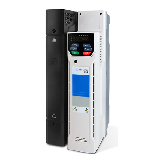
Sigmatek FDD
Step By Step Guide
Schritt-für-Schritt-Anleitung
Frame sizes 5 to 9
Baugrößen 5 bis 9
This guide provides a fast and simple start-up procedure for a basic drive and motor installation
Please read the safety information booklet supplied with the drive before installation or set-up. For FDD3, it is
essential to read
Section 4.6
systems.
Diese Anleitung bietet Informationen für eine schnelle Inbetriebnahme eines einfachen Umrichter-Motor-Systems.
Bitte lesen Sie vor der Installation oder Inbetriebnahme das mit dem Antrieb gelieferte Sicherheitshandbuch.
Für den FDD3 müssen Sie unbedingt
die Funktion Safe Torque Off in Sicherheitssystemen verwenden.
the control User Guide prior to using the SafeTorque Off function in safety
Abschnitt 4.6
des Benutzerhandbuchs der Steuerung lesen, bevor Sie
.
Advertisement
Table of Contents

Subscribe to Our Youtube Channel
Related Manuals for SIGMATEK FDD 3054.00300

Summary of Contents for SIGMATEK FDD 3054.00300
- Page 1 Sigmatek FDD Step By Step Guide Schritt-für-Schritt-Anleitung Frame sizes 5 to 9 Baugrößen 5 bis 9 This guide provides a fast and simple start-up procedure for a basic drive and motor installation Please read the safety information booklet supplied with the drive before installation or set-up. For FDD3, it is essential to read Section 4.6...
-
Page 2: Features Of The Drive
English Introduction The SIGMATEK FDD is a simple and flexible range of drives from 0.25 kW to 132 kW in 8 frame sizes and three input voltage ranges (200 V and 400 V.) This Step-by Step guide provides simple step-by-step instructions on how to mount the drive, fuse and cable selection, wiring the drive-up, programming the drive and running the motor in analog input mode or keypad mode on frames 5 to 9. -
Page 3: Step 1: Check The Contents Of The Box
Current Rating : Voltage rating Heavy Duty current rating x10 2 - 200 V (200 - 240 ± 10 %) 4 - 400 V (380 - 480 ± 10 %) SIGMATEK FDD Step By Step Guide Size 5 to 9... -
Page 4: Step 3: Mount The Drive
(101.4 Ib) 1090 mm 1108 mm 259 mm 310 mm 290 mm 66.5 kg 9.0 mm (0.35 in) (42.91 in) (43.62 in) (10.20 in) (12.21 in) (11.42 in) (146.6 Ib) SIGMATEK FDD Step By Step Guide Size 5 to 9... - Page 5 IEC cable sizes assume Copper conductor, PVC insulation, Installation method B2 and ambient NOTE temperature of 40 °C (104 °F). UL cable sizes assume Copper conductor with insulation rated at 75 °C (167 °F). SIGMATEK FDD Step By Step Guide Size 5 to 9...
- Page 6 STEP 5: Remove the terminal cover and finger guard breakouts Using a flat bladed screwdriver, turn the terminal cover locking clip anti-clockwise by approximately 30°. Slide the terminal cover down. Remove terminal cover in direction shown. SIGMATEK FDD Step By Step Guide Size 5 to 9...
- Page 7 Power and ground terminals 6.0 N m (4.4 lb ft) Power and ground terminals 12 N m (8.85 lb ft) 8 and 9 Power and ground terminals 15 N m (11.1 lb ft) SIGMATEK FDD Step By Step Guide Size 5 to 9...
-
Page 8: Power And Ground Connections
The lower terminal block (2) is used for Motor connection. On size 5, the supply and motor ground connections are made using the M5 studs located near the plug-in power connector. Refer to Figure 6-1. SIGMATEK FDD Step By Step Guide Size 5 to 9... - Page 9 Figure 6-2 Size 6 power and ground connections On a size 6, the supply and motor ground connections are made using the M6 studs located above the supply and motor terminals. Refer to Figure 6-2. SIGMATEK FDD Step By Step Guide Size 5 to 9...
- Page 10 Figure 6-3 Size 7 and 8 power and ground connections (size 7 shown) On size 7 and 8, the supply and motor ground connections are made using the M8 studs located by the supply and motor connection terminals. Refer to Figure 6-3. SIGMATEK FDD Step By Step Guide Size 5 to 9...
- Page 11 Figure 6-4 Size 9A power and ground connections 41 42 On size 9A, the supply and motor ground connections are made using the M10 studs located by the supply and motor connection terminals. Refer to Figure 6-4. SIGMATEK FDD Step By Step Guide Size 5 to 9...
-
Page 12: Control Connections
** FDD3 uses ‘Safe Torque Off’ so terminal 11 is unassigned on the FDD3. When using a FDD3 refer to the 'Safe Torque Off' wiring instructions above. After completing step 6 re-fit the terminal cover (refer to step 5). SIGMATEK FDD Step By Step Guide Size 5 to 9... -
Page 13: Step 7: Use The Keypad
To enter Edit Mode, press button Holding increases or decreases value 0.00 Edit Mode (edited digit flashes) SIGMATEK FDD Step By Step Guide Size 5 to 9... -
Page 14: Step 8: Run The Motor
The drive is now ready to run the motor. Set Pr 05 to 'PAd'. Close Safe Torque Off (FDD3). Press the start key Increasing and Press the up and down keys to increase and decrease the speed. decreasing speed Stopping Press the Stop/Reset key SIGMATEK FDD Step By Step Guide Size 5 to 9... - Page 15 400 V drive Def.60: 460 V 575 V drive: 575 V Motor Rated Power Factor 0.00 to 1.00 0.85 Refer to the Control User Guide for further User Security Status LEVEL.1 information SIGMATEK FDD Step By Step Guide Size 5 to 9...
-
Page 16: Appendix A Ul Listing Information
Drives must be installed using cables rated for 75 °C operation, copper wire only. Where possible, UL Listed closed-loop connectors sized according to the field wiring shall be used for all field power wiring connections. SIGMATEK FDD Step By Step Guide Size 5 to 9... -
Page 17: Motor Overload Protection And Thermal Memory Retention
External Class 2 supply The external power supply used to power the 24 V control circuit shall be marked: "UL Class 2". The power supply voltage shall not exceed 24 Vdc. SIGMATEK FDD Step By Step Guide Size 5 to 9... - Page 18 Deutsch Einführung SIGMATEK FDD3 sind einfache und flexible Umrichter mit einer Leistung von 0,25 kW bis 132 kW in 8 Baugrößen und für drei Eingangsspannungen (200 V und 400 V). Diese Schritt-für-Schritt-Anleitung enthält Anweisungen zur Umrichtermontage, Auswahl von Sicherungen und Kabeln, Umrichterverdrahtung, Umrichterprogrammierung und zum Betrieb des Motors im Analogeingangsmodus oder im Tastaturmodus für die Baugrößen 5 bis 9.
-
Page 19: Schritt 1: Verpackungsinhalt Prüfen
A = AC-Eingang und AC-Ausgang Baugröße: E = AC-Eingang und AC-Ausgang (ohne interne Drossel) Nennspannung: Nennstrom: 2 - 200 V (200 - 240 ±10 %) Nennstrom bei hoher Belastung x 10 4 - 400 V (380 - 480 ±10 %) Schritt-für-Schritt-Anleitung SIGMATEK FDD3... - Page 20 259 mm 310 mm 290 mm 9,0 mm 52 kg 1051 mm 1069 mm 259 mm 310 mm 290 mm 9,0 mm 46 kg 1090 mm 1108 mm 259 mm 310 mm 290 mm 9,0 mm 66,5 kg Schritt-für-Schritt-Anleitung SIGMATEK FDD3...
- Page 21 Das Produkt besitzt eine UL-Zulassung für den Einsatz in einem Stromkreis bis max. 100 kA HINWEIS Netzkurzschlussstrom bei Verwendung entsprechender Sicherungen. IEC-Kabelquerschnitte beziehen sich auf einen Kupferleiter, PVC-Isolierung, Installationsmethode B2 HINWEIS und eine Umgebungstemperatur von 40 °C. UL-Kabelquerschnitte beziehen sich auf einen Kupferleiter mit Isolierung bei 75 °C. Schritt-für-Schritt-Anleitung SIGMATEK FDD3...
- Page 22 SCHRITT 5: Klemmenabdeckung abnehmen und Ausbrüche der Kabeleinführungen entfernen Drehen Sie die Verriegelung der Klemmenabdeckung mit einem Schlitzschraubendreher um etwa 30° gegen den Uhrzeigersinn. Schieben Sie die Klemmenabdeckung nach unten. Entfernen Sie die Klemmenabdeckung in der dargestellten Richtung. Schritt-für-Schritt-Anleitung SIGMATEK FDD3...
- Page 23 0,2 N m Alle Relaisklemmen 0,5 N m Klemmenanschlüsse - Leistung 1,5 N m Erdungsanschlüsse 2,0 N m Strom- und Erdanschlussklemmen 6,0 N m Strom- und Erdanschlussklemmen 12 N m 8 und 9 Strom- und Erdanschlussklemmen 15 N m Schritt-für-Schritt-Anleitung SIGMATEK FDD3...
- Page 24 Der obere Klemmenblock (1) wird für die Netzversorgung verwendet. Der untere Klemmenblock (2) wird für den Motoranschluss verwendet. Bei Umrichtern der Baugröße 5 wird die Erdung von Netz- und Motoranschluss durch die M5- Erdungsbolzen neben den Netzanschlussklemmen vorgenommen. Siehe Abbildung 6-1. Schritt-für-Schritt-Anleitung SIGMATEK FDD3...
- Page 25 Abbildung 6-2 Baugröße 6 – Strom- und Erdungsanschlüsse Bei Umrichtern der Baugröße 6 wird die Erdung von Netz- und Motoranschluss durch die M6- Erdungsbolzen vorgenommen, die sich über den Netz- und Motoranschlussklemmen befinden. Siehe Abbildung 6-2. Schritt-für-Schritt-Anleitung SIGMATEK FDD3...
- Page 26 Abbildung 6-3 Baugrößen 7 und 8 – Strom- und Erdungsanschlüsse (Abbildung zeigt Baugröße 7) Bei Umrichtern der Baugröße 7 bis 8 wird die Erdung von Netz- und Motoranschluss durch die M8- Erdungsbolzen vorgenommen, die sich über den Netz- und Motoranschlussklemmen befinden. Siehe Abbildung 6-3. Schritt-für-Schritt-Anleitung SIGMATEK FDD3...
- Page 27 Abbildung 6-4 Baugröße 9A - Leistungswerte und Erdverbindungen Bei Umrichtern der Baugröße 9A wird die Erdung von Netz- und Motoranschluss durch die M10- Erdungsbolzen vorgenommen, die sich über den Netz- und Motoranschlussklemmen befinden. Siehe Abbildung 6-4. Schritt-für-Schritt-Anleitung SIGMATEK FDD3...
- Page 28 > 16 mm² und ≤ 35 mm² 16 mm² Der halbe Querschnitt des Leitungsquerschnitts des Netzanschlusses. > 35 mm² Steueranschlüsse Die Steueranschlussklemmen sind standardmäßig für die nachstehend gezeigte Anordnung konfiguriert: Abbildung 6-5 SIGMATEK FDD2/FDD3 Steuerklemmenbelegung Digitale E/A Analoge Ein- und Ausgänge 24-V-Abnehmer Digitaler Ein-/...
- Page 29 , um den neuen Parameterwert zu ignorieren und den Parameterwert auf den Wert vor der Bearbeitung zurückzusetzen Zum Wechseln in den Bearbeitungsmodus die Taste drücken Durch Halten von oder wird der Wert erhöht bzw. verringert (bearbeitete Ziffer blinkt) Eingabemodus Schritt-für-Schritt-Anleitung SIGMATEK FDD3...
- Page 30 Der Umrichter ist nun zum Starten des Motors bereit. Setzen Sie Pr 05 auf ‚PAd‘. Schließen Safe Torque Off (FDD3). Drücken Sie die Start-Taste Erhöhen und Drücken Sie die Auf- und Ab-Tasten , um die Drehzahl zu erhöhen bzw. zu Verringern der verringern. Drehzahl Anhalten des Drücken Sie die Stopp/Reset-Taste Motors Schritt-für-Schritt-Anleitung SIGMATEK FDD3...
- Page 31 200-V-Umrichter: 230 V Motornennspannung 0 bis 530 V 400-V-Umrichter Def.50: 400 V 0 bis 635 V 400-V-Umrichter Def.60: 460 V 575-V-Umrichter: 575 V Motorleistungsfaktor 0,00 bis 1,00 0,85 Weitere Informationen können der Betriebsanleitung: Benutzersicherheitsstatus LEVEL.1 Steuereinheit entnommen werden. Schritt-für-Schritt-Anleitung SIGMATEK FDD3...
-
Page 32: Montage
Die Umrichter sind für den Betrieb in einer Schaltung geeignet, die nicht mehr als 100.000 RMS symmetrische Ampere bei einer maximalen Spannung von 600 VAC leistet. KLEMMEN-ANZUGSMOMENT Klemmen müssen mit dem in den Installationsanweisungen angegebenen Anzugsmoment angezogen werden. VERDRAHTUNG DER KLEMMEN Schritt-für-Schritt-Anleitung SIGMATEK FDD3... - Page 33 EINSCHWINGSPANNUNGSSTÖSSEN MIT EINER NENNSPANNUNG VON 575 VAC (PHASE ZU ERDE) BZW. 575 VAC (PHASE ZU PHASE) SOWIE EINER EIGNUNG FÜR DIE ÜBERSPANNUNGSKATEGORIE III INSTALLIERT WERDEN. AUSSERDEM MUSS DAS SYSTEM EINEN NENNSTOSSSPANNUNGSSCHUTZ MIT EINEM SPITZENWERT VON 6 KV AUFWEISEN UND EINER KLEMMENSPANNUNG VON MAXIMAL 2400 V WIDERSTEHEN. Schritt-für-Schritt-Anleitung SIGMATEK FDD3...
- Page 34 0478-0637-04...
Need help?
Do you have a question about the FDD 3054.00300 and is the answer not in the manual?
Questions and answers