
Subscribe to Our Youtube Channel
Summary of Contents for Shimadzu Hyper Vision HPV-X2
- Page 1 347-07040 May. 2015 High-Speed Video Camera Hyper Vision HPV-X2 Instruction Manual Read the instruction manual thoroughly before you use the product. Keep this instruction manual for future reference.
-
Page 3: Introduction
"Safety Instructions" before you use the product. Any export of Shimadzu High-Speed Camera, HPV-X is subject to export control regulations of the nation, based on Part2 of NSG guideline, 5.B.3. Please contact sales agent or representative of Shimadzu, should you have any question. -
Page 4: Indications Used In This Manual
Indications Used in This Manual Warnings, Cautions, and Notes are indicated using the following conventions: Indicates a potentially hazardous situation which, if not avoided, could Warning result in serious injury or possibly death. Indicates a potentially hazardous situation which, if not avoided, may Caution result in minor to moderate injury or equipment damage. -
Page 5: Safety Instructions
High-Speed Video Camera HPV-X2 Safety Instructions To ensure safe product operation, read these important safety instructions carefully before use and follow all WARNING and CAUTION instructions given in this section. Installation Site Warning ● Avoid humidity and dust Do not place the product in an environment with high humidity or dust. This may result in fire or electric shock. -
Page 6: Installation
Do not place heavy objects on, alter, forcibly bend, twist, pull, or heat the power cable. This can damage the power cable, resulting in fire or electric shock. If the power cable is damaged (exposed or broken wires), contact your Shimadzu representative for a replacement. Using a damaged cable may result in fire or electric shock. -
Page 7: Operation
When the power cable is damaged Continuing to use the product in this condition may result in fire or electric shock. Immediately contact your Shimadzu representative. ● Avoid operation in strong electromagnetic fields Do not use the product in locations subject to strong electromagnetic fields. This may result in incorrect or abnormal operation. -
Page 8: Inspection And Maintenance
Doing so may result in electric shock. ● Do not disassemble or modify Do not disassemble or modify the product. Doing so may result in fire or electric shock. Contact your Shimadzu representative for inspection, servicing or repair of the product inside. Caution ●... -
Page 9: Emergency Measures
To ensure the safe operation of this product, warning labels are attached in locations where caution is required. If a warning label is lost or damaged, obtain a new label through your Shimadzu representative and attach it in the correct position. -
Page 10: Residual Risk Information
Residual Risk Information Residual Risk Map Mechanical Location A No.1 Residual Risk List Preparations Protective Measure Mechanical Description taken by machine user Location P.10 Reference Attaching Operation The camera is fixed Fixing to a tripod is Category Camera tightly at a fixed screw insufficient and the... -
Page 11: Warranty
Shimadzu has been advised of the possibility of such damage. -
Page 12: Software License Agreement
PLEASE READ THIS AGREEMENT CAREFULLY BEFORE USING THE SOFTWARE. SHIMADZU Corporation (“SMZ”) is willing to license the SMZ software provided herein, together with accompanying documentation (collectively “SOFTWARE”) to you only upon the condition that you accept all of the terms and condition contained in this License Agreement. -
Page 13: After-Sales Service And Availability Of Replacement Parts
Replacement parts for this product will be available for a period of seven (7) years after the product is discontinued." Thereafter, such parts may cease to be available. Note, however, that the availability of parts not manufactured by Shimadzu shall be determined by the relevant manufacturers. Maintenance, Inspections, and Adjustment In order to maintain the instrument's performance and obtain accurate recording data, daily inspection and periodic inspection are necessary. -
Page 14: Patents
Patents This product has licences of the following US PATENTs 5,471,515 6,107,618 6,476,860 6,825,059 5,793,322 6,107,619 6,486,503 6,838,301 5,841,126 6,115,065 6,515,702 6,839,452 5,880,691 6,124,819 6,519,371 6,933,488 5,886,659 6,166,768 6,546,148 6,943,838 5,887,049 6,175,383 6,549,235 6,944,352 5,909,026 6,326,230 6,555,842 6,980,230 5,929,800 6,346,700 6,570,617 7,002,626 5,949,483... -
Page 15: Table Of Contents
High-Speed Video Camera HPV-X2 Contents Introduction ..................i Indications Used in This Manual ............ii Safety Instructions ................iii Installation Site ................iii Installation ..................iv Operation ..................v Inspection and Maintenance ............vi Emergency Measures ..............vii ... - Page 16 4.7.1 Shutting Down Without a Camera Connected ......26 4.7.2 Shutting Down with a Camera Connected ........26 Operating the Camera ............... 29 Operation Flowchart ..............29 Camera Settings................30 Illumination Settings ..............30 Recording Images ................ 31 5.4.1 Setting Recording Parameters............31 5.4.2 Adjusting Exposure ...............
-
Page 17: Product Overview
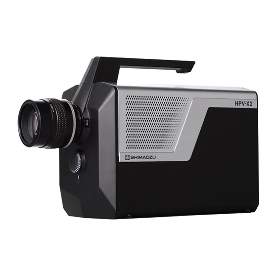
High-Speed Video Camera HPV-X2 Product Overview This high-speed video camera is capable of recording and playing up to 256 serial images as moving images at speeds of up to ten million frames per second. The HPV-X2 consists of a camera head with high-performance FTCMOS image sensor, a power unit, and a control computer (Windows 7 based. -
Page 19: Names And Functions Of Components
High-Speed Video Camera HPV-X2 Names and Functions of Components Instrument Composition The HPV-X2 comprises the following units and parts. When unpacking, make sure that all of these items are included. (1) Camera head (2) Power unit... - Page 20 (3) Ethernet cable (4) Power cable (11) Synchronization cable (5) AC cable (For US) (5) AC cable (For EU) (6) Control computer (sold separately) Table 2-1 List of Components Part Name Q'ty Camera head Power unit Ethernet cable Power cable AC cable (For US or For EU) Control computer (sold separately)
-
Page 21: Control Computer (Application) Functions
High-Speed Video Camera HPV-X2 Control Computer (Application) Functions ■ Image Display Window (Playback Parameter Settings Window) This window (Fig. 2-1) is used to playback recorded images, manage image files, and perform other operations. Image monitor (image display area) Displays recorded images and live images. ... - Page 22 ■ Recording Parameter Settings Window This window is used for specifying recording parameters. Recording parameters are specified via [REC] (Fig. 2-2) and [I/O PORT] (Fig. 2-3) windows. It also starts recording and operates live functions. Recording parameter settings Fig. 2-2 [REC] Window Recording parameter settings Fig.
-
Page 23: Names And Functions Of Parts - Camera Head
High-Speed Video Camera HPV-X2 Names and Functions of Parts – Camera Head The camera consists of the camera head and lens (optional). The camera head accepts Nikon F-mount compatible lenses. The following figures show the camera head and its parts. (6) Camera status indicator LEDs (5) Trigger input connector (BNC) - Page 24 (9) F lens mount (10) Handle (11) Camera head tripod mount Side view of camera head Fig. 2-5 Camera Head (Continued) Caution ● Do not apply a voltage exceeding the range of 5V-TTL level on the trigger input connector and the standby input connector. There is a risk that the device fails or does not work correctly Part Name Description...
- Page 25 High-Speed Video Camera HPV-X2 Part Name Description 3.3k TC74VHCT14A Trigger input connector Connector used to input the trigger signal (BNC) The trigger input can be a TTL 5 V signal or normally open contact input. (MAKE ON) 3.3k TC74VHCT14A Camera status indicator These indicate the camera status.
-
Page 26: Names And Functions Of Parts - Power Unit
Names and Functions of Parts – Power Unit The Power unit supplies power to the camera head. (1) LED Power supply unit side view Power supply unit front view (2) Power switch (4) Power cable connector (3) AC cable connector Power supply unit rear view Fig. -
Page 27: Specifications
High-Speed Video Camera HPV-X2 Specifications ■ Camera Head 1) Lens Mount Nikon F mount Image Sensor FTCMOS2 image sensor ) HP mode 10 Mfps, 5 Mfps (fixed) Recording Speed (frame rate) FP mode 5 Mfps (fixed) Variable recording speed (in a 1/(10 ns) interval) Both modes in a range from 60 fps to 2 Mfps Continuous Recording... - Page 28 (Between Camera and Approx. 2.8 m Power Unit) Shimadzu does not guarantee that all F-mount lenses can be attached. The recording speed is a reference value. It is not guaranteed to be an accurate value for the time interval between recording frames.
-
Page 29: Preparations For Operation
High-Speed Video Camera HPV-X2 Preparations for Operation Connecting Cables Warning ● To avoid electric shock, be sure to insert cables in a socket that is equipped with a grounded terminal. Failure to do so may result in electric shock. ● To avoid electric shock if a 3-to-2 prong plug adapter is used, be sure to connect the adapter ground wire to ground. -
Page 30: Mounting And Removing Lenses
Mounting and Removing Lenses ■ Mounting the Lens Remove lens caps from the lens and camera head. Fig. 4-2 Camera Head and Lens Firmly hold the lens, and align the lens with the camera head mount. Fig. 4-3 Mounting the Lens 1... - Page 31 High-Speed Video Camera HPV-X2 Insert the lens into the camera head mount with the dot mark on top of the lens turned clockwise about 30 degrees. ✐ Note Position the lens so that it fits without leaving a clearance between the lens and camera head mount.
- Page 32 We also recommend using a jig or other support device to prevent applying any excessive loads on the mount. Excessive loads could damage the mount. Shimadzu does not guarantee that all F-mount lenses can be attached.
- Page 33 High-Speed Video Camera HPV-X2 ■ Lenses with an Aperture Ring If using a lens with an aperture ring, align the aperture dial on the front of the camera head to [CLOSE] and use ring on the lens to adjust the aperture. Fig.
- Page 34 ■ Lenses Without an Aperture Ring If using a lens without an aperture ring, use the dial on the front of the camera head to adjust the aperture. Fig. 4-10 Lens without Aperture Ring Adjust the aperture using the aperture dial.
-
Page 35: Starting Up The High-Speed Video Camera
High-Speed Video Camera HPV-X2 Starting Up the High-Speed Video Camera Hold down the power button on the power unit for three seconds to switch ON the camera system. Switch the control computer ON. Log in to Windows. (See Logging In and Out of Windows.) Double-click the icon on the desktop. - Page 36 ■ Logging Out of Windows Click the [Start] button (1) on the taskbar. Click button (2) on the Start menu. The shutdown options menu is displayed. Fig. 4-12 Logging Out of Windows Select the desired logoff option. Selecting [Shut down] Windows closes all open applications and switches OFF power to the control computer.
-
Page 37: Connecting To A Network
For more details about the settings, refer to the Windows help files or User's Guide. ✐ Note Shimadzu assumes no warranty for security problems that may arise from a permanent network connection. Also, Shimadzu cannot guarantee the installation or normal operation of antivirus software or network security software on the control computer. - Page 38 After selecting the cameras to be connected from the list, click [IP address of the camera] – [Copy]. This lists IP addresses for cameras being connected in [IP address of the camera] field.
-
Page 39: Procedure For Changing The Ip Address Of The Camera
High-Speed Video Camera HPV-X2 In the [IP address of the computer to set the network where a camera is connected to] field, select the IP address of the computer. After selecting the computer IP address, click [OK] to finish registration. 4.6.2 Procedure for Changing the IP Address of the Camera Double-click the [HPV-X Setting] shortcut on the desktop to display the following... - Page 40 Clicking [Search cameras on the network] lists all cameras on the network. In the list, select the camera IP address to change. After selecting the camera IP address to change, click [IP address of the camera].
- Page 41 High-Speed Video Camera HPV-X2 The following window is displayed. Change the IP address and subnet mask settings as desired and click [OK]. Finish the procedure by verifying that the corresponding camera IP address appears changed in the list.
-
Page 42: Shutting Down The High-Speed Video Camera
Shutting Down the High-Speed Video Camera 4.7.1 Shutting Down Without a Camera Connected Click in the Viewer window. If no other Viewer windows are displayed, a shutdown confirmation dialog box is displayed. If another Viewer window is displayed, the shutdown confirmation dialog box is not displayed. - Page 43 High-Speed Video Camera HPV-X2 Hold down the power button on the power unit for three seconds to switch OFF power to the camera system. Click here to close the application. [EXIT] Fig. 4-14 Recording Parameter Settings Window Fig. 4-15 Shutdown Confirmation Dialog Box ✐...
-
Page 45: Operating The Camera
High-Speed Video Camera HPV-X2 Operating the Camera This section describes how to operate the camera. Operation Flowchart Fig. 5-1 shows a process flowchart of operating cameras. For details about operation, see the instructions in 5.2 Camera Settings and thereafter See 5.2 Camera Setup. Set up camera. -
Page 46: Camera Settings
Camera Settings Use the live image to adjust the viewing angle and focal point, as follows. Position the camera head while viewing the live image to make sure the desired view is properly within the viewing frame. Adjust the focus on the object being recorded by turning the focus ring on the lens. -
Page 47: Recording Images
High-Speed Video Camera HPV-X2 Recording Images ■ Actual Recording Procedure Set the recording parameters. Click [REC] in the Viewer window or the recording parameter settings window. Input the standby OFF trigger signal. The standby OFF trigger signal can be delayed by a preset delay time. (This does not need to be input for the external trigger mode [External TRIG] or continuous external trigger mode [R-External TRIG]. - Page 48 Name Description Page [Auto Save Setting] selects the format for saving recording data. ③ Displays version information. P.35 Version Information Display Icon ④ Closes the application. P.35 EXIT ⑤ Window Display Mode Switches between windows for recording parameter P.35 settings ⑥...
- Page 49 High-Speed Video Camera HPV-X2 Fig. 5-4 Window for Loading Files Saving recording parameter setting files – [Save Setting File] Clicking [Save Setting File] displays a window for saving files (Fig. 5-5). Enter a file name and click [Save] to save the current recording parameter settings with the specified file name.
- Page 50 Selecting the format for saving recording data – [Auto Save Setting] Clicking [Auto Save Setting] displays a window for selecting the format used to save recording data (Fig. 5-6). Specify the format for saving image files after recording, specify whether or not to display time information in images, specify whether or not to display the relative time with respect to trigger input in images, and specify settings for saving metadata for image files.
- Page 51 High-Speed Video Camera HPV-X2 ■ Displaying Version Information Clicking the icon displays the version information display window (Fig. 5-7). Click [CLOSE] to close the window. Fig. 5-7 Version Information Display Window ■ Closing the Application[EXIT] Click the icon to close the application. (See 4.7.2 Shutting Down with a Camera Connected.) ■...
- Page 52 Recording parameter settings Clicking the [REC] Recording mode : External standby mode [External STANDBY] Recording frames : 128frames : 850ns + Xns Standby delay [Recording] [Ends] Standby delay Standby Signal [Waiting for standby signal] (850ns) Frame No. 127 128 Sensor wake up time Fig.
- Page 53 High-Speed Video Camera HPV-X2 Recording parameter settings Clicking the [REC] Recording mode : External separate mode [External SAPARATE] Recording frames : 128frames Trigger point Trigger delay Standby delay : 850ns [Ends] [Recording] Standby Signal [Waiting for standby signal] Trigger Signal [Waiting for trigger signal]...
- Page 54 trigger signal is input, it records the specified number of frames and reads the image data. Then it immediately starts waiting for input of the next standby signal. This process is then repeated. Continuous external SYNCIN mode – [R-External SYNCIN] This mode allows repeatedly recording images using the external SYNCIN mode.
- Page 55 High-Speed Video Camera HPV-X2 ■ Selecting the Recording Frame in [REC] – [FRAMES] Clicking the icon displays [128] and [256] settings. ■ Selecting the Recording Speed in [REC] – [SPEED] Set the recording speed by clicking [REC] – [SPEED]. The default recording speed setting after initial startup can be selected from 100 ns, 200 ns, 500 ns, 1,000 ns, 2,000 ns, 5,000 ns, 10,000 ns, 20,000 ns, 50,000 ns, 100,000 ns, 2,000,000 ns, 5,000,000 ns, or 16,666,670 ns.
- Page 56 To not save the settings, click [CANCEL]. Changing the units for displaying recording speed Display the window for editing the recording speed selection list (Fig. 5-11). Select either [ns] or [fps] in the [UNIT] field. Click [OK]. Save the settings and close the window. Once the settings are saved, [REC] – [SPEED] values are displayed in terms of the changed units.
- Page 57 High-Speed Video Camera HPV-X2 ■ Selecting Exposure Time for Recording in [REC] – [EXPOSE] Exposure time for recording is selected in the [REC] – [EXPOSE] field. The default recording exposure time setting after initial startup is selectable from 200 ns, 500 ns, 1,000 ns, 2,000 ns, 5,000 ns, 10,000 ns, 20,000 ns, 50,000 ns, 100,000 ns, 1,000,000 ns, 2,000,000 ns, 5,000,000 ns, or 10,000,000 ns.
- Page 58 Initializing the recording exposure time selection list (default settings) Display the window for editing the exposure time selection list (Fig. 5-12). Clicking [<< Default] displays a confirmation dialog box. Click [Yes]. Clicking [Yes] resets the [LIST] values to default settings. Default values are 200 ns, 500 ns, 1,000 ns, 2,000 ns, 5,000 ns, 10,000 ns, 20,000 ns, 50,000 ns, 100,000 ns, 1,000,000 ns, 2,000,000 ns, 5,000,000 ns, and 10,000,000 ns.
- Page 59 High-Speed Video Camera HPV-X2 ■ Setting the Trigger Point in [TRIGGER] – [POINT] Select the frame for trigger detection in the [TRIGGER] – [POINT] field. It saves data from before and after the trigger signal. Enter the trigger point setting values using the keyboard or mouse.
- Page 60 ■ Setting Polarity of External Signal (Standby OFF) in [STANDBY] – [POLARITY] This setting is not necessary for the trigger mode [Internal], [External TRIG], [External SYNCIN], [R-External TRIG] or [R-External SYNCIN]. External signals (triggers) can be input in two ways – either as step up (POS) or step down (NEG) signals.
- Page 61 High-Speed Video Camera HPV-X2 To not save the settings, click [CANCEL]. Procedure for deleting settings from the live image exposure time selection list Display the window for editing the live image exposure time selection list (Fig. 5-14). Select the live image exposure time setting to delete from the [LIST]. Click [Delete >>] to delete the selected live image exposure time setting from the [LIST] field.
- Page 62 ■ External Output Ports 1 and 2 in [AUXOUT1] or [AUXOUT2] – [MODE] ⑨ ② ① ⑤ ⑥ ③ ④ ⑧ ⑦ Fig. 5-15 [I/O PORT] Window Name Description Page ① [AUXOUT1 MODE] Select the mode for external output port 1. P.46 ②...
- Page 63 High-Speed Video Camera HPV-X2 EXPOSE END Outputs the starting point of the exposure period for the last frame during recording. TRIG STANDBY Outputs a standby signal. (Does not include standby delay time, even if specified in [STANDBY] – [DELAY].) ...
-
Page 64: Adjusting Exposure
■ Adjusting the Pulse Width for External Output Ports in [AUXOUT1] or [AUXOUT2] – [PULSE] This setting is unnecessary if [STATUS STANDBY], [STATUS TRIG], or [STATUS REC] is selected as the external output port mode in [AUXOUT1] or [AUXOUT2] – [MODE]. -
Page 65: Recording
High-Speed Video Camera HPV-X2 5.4.3 Recording ✐ Note Sensor elements generate heat during recording. Therefore, to protect the sensor elements from heat when recording at speeds of 5Mfps or more, in all recording modes except the internal trigger mode [Internal], recording is stopped if a trigger signal is not detected within 60 seconds in waiting a trigger signal. - Page 66 ■ Recording in the External Trigger Mode [External SEPARATE] This mode is a combination of the external standby and external trigger modes. It is used to record images after the camera has been in standby a long time. In "Selecting the Recording Mode in [REC] – [MODE]" in 5.4.1 Setting Recording Parameters, specify the external trigger mode [External SEPARATE] to use as the recording mode.
- Page 67 High-Speed Video Camera HPV-X2 ■ Recording in the Continuous External Trigger Mode [R-External SEPARATE] This mode allows repeated recording using the external separate mode [External SEPARATE]. In "Selecting the Recording Mode in [REC] – [MODE]" in 5.4.1 Setting Recording Parameters, specify the continuous external trigger mode [R-External SEPARATE] to use as the recording mode.
-
Page 68: Synchronized Recording
5.4.4 Synchronized Recording This function enables recording in synchronized frame timing by connecting two cameras using a synchronization cable. The cameras can be distinguished as the master camera that sends signals and the slave camera that receives signals by setting how the synchronization cable is connected. When the cover on the rear of the camera is removed, then the synchronization signal input and output connectors can be found. - Page 69 High-Speed Video Camera HPV-X2 The camera with the synchronization cable connected to its synchronization signal output connector becomes the master camera and the camera with the synchronization cable connected to its synchronization signal input connector becomes the slave camera. Synchronization cable Fig.
- Page 70 ■ Recording in the Continuous External Trigger Mode [R-External SYNCIN] This mode allows repeatedly recording frames using the external trigger mode [External SYNCIN]. This section describes recording when the master camera is set in the external trigger mode [External SEPARATE]. First, configure settings on the slave camera.
-
Page 71: Playing Back Images
High-Speed Video Camera HPV-X2 Playing Back Images The HPV-X software immediately displays recorded images as moving images. Images can also be played back one frame at a time by manual operation. Before playing back moving images, click [DETAIL] in Viewer and set the playback parameters. - Page 72 Name Description Page ⑮ Restores default settings. P.58 ⑯ Switches window display mode. P.58 / ⑰ Zoom Rate Sets image display magnification setting. P.59 ⑱ Organizes Viewer windows into rows and columns. P.60 ⑲ Displays details. P.60 ■ Play/Stop ( Plays back the currently displayed image.
- Page 73 High-Speed Video Camera HPV-X2 ■ Display Angle Setting [ROTATE] Images can be rotated by 0 degree, 90 degree, 180 degree, or 270 degree, or mirrored. ■ Repeated Playback Setting [REPEAT] Set whether or not to repeat playback. Playback is repeated when [REPEAT] is selected. When [REPEAT] is not selected, images are only played back once.
- Page 74 ■ Default Settings ( Restores playback parameter settings to their default values. Clicking the con displays the default value setting confirmation window (Fig. 5-20). Clicking [Yes] sets playback parameter settings to their default values. Clicking [No] cancels restoring default values. Fig.
- Page 75 High-Speed Video Camera HPV-X2 ■ Zoom Rate Zoom rate of displayed image Displays the magnification rate of the currently displayed image. Zoom In (This icon is not available when there is no image data displayed in Viewer.) This icon enlarges the displayed image. The magnification rate can be set to x1.5 or x2 the current magnification of the displayed image.
-
Page 76: Playing Back Images
■ Details Display (This icon is not available when there is no image data displayed in Viewer.) This icon displays detailed information (e.g. recording parameters) of the currently displayed image data (Fig. 5-22). To close the detailed information confirmation window, click the icon or click icon again. -
Page 77: Image File Management And System Shutdown
High-Speed Video Camera HPV-X2 Image File Management and System Shutdown On the HPV-X sofware, recorded images can be saved as image files. File operations allow files to be displayed, unwanted files to be deleted, and files to be converted. To perform file operations, click the file operation list icon in Viewer and select the desired operation and image file. - Page 78 ✐ Note If the Viewer window is not interlocked to the camera and the recorded image is not displayed, the confirmation window in Fig. 5-19 is not displayed. In that case, the recorded image is displayed unconditionally in the currently active Viewer window. Clicking [Yes] or [No] displays a window for opening files (Fig.
- Page 79 High-Speed Video Camera HPV-X2 Fig. 5-26 File Conversion Window (CONVERT) ✐ Note If a TIFF (16-bit) image cannot be displayed correctly in the currently active Viewer, change the "Tiff16Upper=" [Auto Save Setting] to either "0" or "1" in the "HPVX.ini" file, located in the same folder as the "HPVX.exe"...
-
Page 80: Saving Image Files
5.6.2 Saving Image Files This section describes the procedure for saving recorded images (Figs. 5-28, 5-29, and 5- 30). Factory settings save images to the "Image" folder on the C: drive. To save images on a different drive, change the "C" or other drive name indicated in the "ImagePath=C:¥Image"... - Page 81 High-Speed Video Camera HPV-X2 Table 5-1 Space Requirements for Image Files Number of Format Space Required Frames Dedicated 16-bit (dat) About 25 Mbyte About 12 Mbyte jpeg About 300 Kbyte avi8 About 12 Mbyte avi24 About 36 Mbyte tiff About 400 Kbyte tiff16 About 25 Mbyte Dedicated 16-bit (dat)
- Page 82 Click [Save]. When overwriting a file, the original DAT file is updated. If the file name is changed, the DAT file is created in the current directory using the new file name. To not save the file, click [Cancel]. Fig. 5-29 Window for Saving Files 1 (SAVE) ■...
- Page 83 High-Speed Video Camera HPV-X2 Click [Save]. If saving to a file format other than DAT, a folder named for the specified file format (such as "BMP" folder or folder named based on the file name if BMP format is specified) is created in the destination folder. Then the converted image file is saved in these folders.
-
Page 84: Closing The Application
5.6.3 Closing the Application Clicking the icon in the recording parameter settings window displays a shutdown confirmation dialog box (Fig. 5-32). To exit the application, click [Yes]. To cancel the exit, click [No]. For instructions on how to log out, see 4.4 Logging In and Out of Windows. Fig. -
Page 85: Input/Output File Formats
High-Speed Video Camera HPV-X2 Input/Output File Formats 5.7.1 Image File Formats ■ File Composition Description Proprietary format for saving both recorded images and metadata Saved after recording is finished. Item Size Data tag 4 byte Type of data 2 byte 0:CHAR(INT8)... - Page 86 Data Content Tag Entries Remarks Data Tag Type of Data Data Count (4 byte) (2 byte) (4 byte) Gamma correction 0x2020, Setting value: 30 to 300 factor 0x2006 (1/100) Brightness 0x2020, Setting value: -100 to 100 0x2007 Contrast 0x2020, Setting value: 50 to 200 0x2008 (1/100) Recording mode (on UI)
- Page 87 High-Speed Video Camera HPV-X2 Data Content Tag Entries Remarks Data Tag Type of Data Data Count (4 byte) (2 byte) (4 byte) Standby OFF input 0x3030, Setting value: (Character delay setting 0x300D string) 100 to 9999999990 (in 10 ns steps of 1 ns units) Synchronized (internal) 0x3030, Setting value: (Character...
- Page 88 Data Content Tag Entries Remarks Data Tag Type of Data Data Count (4 byte) (2 byte) (4 byte) CamName 0x4040, Setting value: (Character Camera name 0x4001 string) Camera names settable in the recording parameter settings window CamSerialNumber 0x4040, Setting value: (Character Camera serial number 0x4002 string)
- Page 89 High-Speed Video Camera HPV-X2 Data Content Tag Entries Remarks Data Tag Type of Data Data Count (4 byte) (2 byte) (4 byte) applicable recording mode was created Sensor 0x5050, Setting value: (Character Applicable sensor 0x5003 string) number Camera sensor number RecMode 0x5050, Setting value: (Character...
-
Page 90: Metadata In Image Files
5.7.2 Metadata in Image Files ■ File Composition Description File used to save metadata for image files as text. Auto Save Setting function ( ) in the recording parameter settings window allows specifying saving files after recording. File Structure INI format Data Elements Section, key Example:... - Page 91 High-Speed Video Camera HPV-X2 Section Remarks StandbyPolarity Example: STANDBY signal (standby OFF) input StandbyPolarity =POS logic StandbyDelay Example: STANDBY signal (standby OFF) delay StandbyDelay =10,000,000 ns time in ns units PortAuxout1Mode Example: External output port 1 mode PortAuxout1Mode =EXPOSE STANDBY PortAuxout1Polarity Example: External output port 1 input logic...
-
Page 92: Recording Parameter Setting Files
5.7.3 Recording Parameter Setting Files ■ File Composition Description File used to save recording parameters in the recording parameter settings window as text. Read/write using Open Setting File ( ) and Save Setting File functions in the recording parameter settings window. File Structure INI format Data Elements... - Page 93 High-Speed Video Camera HPV-X2 Section Remarks StandbyPolarity Example: Standby signal polarity setting StandbyPolarity=0 Setting value: 0:NEG 1:POS StandbyDelay Example: Standby signal delay time StandbyDelay=100 PortAuxout1Mode Example: External output port 1 mode setting PortAuxout1Mode=0 Setting value: 0:EXPOSE REC 1:EXPOSE LIVE 2:EXPOSE BOTH 3:EXPOSE STANDBY 4:EXPOSE TRIG 5:EXPOSE END...
-
Page 94: Displaying Version Information
Section Remarks PortAuxout2Delay Example: External output port 2 delay time setting PortAuxout2Delay=0 PortAuxout2Pulse Example: External output port 2 signal width setting PortAuxout2Pulse=50 Displaying Version Information The following describes how to display version information. If a camera is connected, click the icon in the recording parameter settings window or activate an application window and press the [F1] key to display the version information display window (Fig. -
Page 95: Maintenance
Disconnected cable Correctly connect the cable. switch ON. Fuse in power unit blown The problem is presumably in the electrical system. Therefore, contact a Shimadzu service representative. Try moving the lighting closer or increasing Recorded image Insufficient light during the brightness setting. (See 5.2 Camera appears dark. -
Page 96: Unit Cleaning
Unit Cleaning Warning ● Always disconnect the power cable before cleaning the product. Failure to do so may result in electric shock. ✐ Note Do not use volatile solvents (paint thinner, benzene, etc.) or a damp cloth to clean the product. Use a soft, dry cloth. -
Page 97: Index
High-Speed Video Camera HPV-X2 Index A R AUX Output Connector ..........7 REC MODE ............37 Recording Images ..........33 B S BRIGHTNESS ............59 Saving Image File ..........66 C Setting Playback Parameters ........57 Standby Input Connector.......... 7 Camera Status Indicator ...........
Need help?
Do you have a question about the Hyper Vision HPV-X2 and is the answer not in the manual?
Questions and answers