Table of Contents
Advertisement
Quick Links
Advertisement
Table of Contents

Related Manuals for Bastian Solutions RLCDC


Summary of Contents for Bastian Solutions RLCDC
- Page 1 Installation and Maintenance Manual Model: RLCDC Effective February 2022 Rev. B...
- Page 2 Installation and Maintenance Manual: RLCDC Contributions ROLE NAME TITLE Author Sam Osterhout Project Engineer Checker Josh Foiles Design Engineer Approver Chris Perry Engineering Manager Revisions DATE REVISION DESCRIPTION AUTHOR 10/28/2019 Initial Document Creation Sam Osterhout 10/8/21 Reformatting and Brand Update...
- Page 3 Installation and Maintenance Manual: RLCDC Term and Acronym Definitions TERM/ACRONYM DEFINITION Roller format which uses O-Rings to transfer rotational motion from one 2 Groove roller to another in DC conveyor. Between frame; this refers to the distance between conveyor bed side frames.
-
Page 4: Table Of Contents
Figure 5: MDR Removal-2 ........................14 Figure 6: MDR Removal-3 ........................15 Figure 7: O-ring Band Replacement ....................... 16 Figure 8: RLCDC Standard Spare Parts Exploded View ................. 18 List of Tables Table 1: MDR Nut Torque Specifications ....................11 Table 2: Troubleshooting Card Issues .................... - Page 5 Installation and Maintenance Manual: RLCDC Reference Documents MANUFACTURER MANUAL Interroll 9006 Hybrid Control for RollerDrive Manual Interroll ZoneControl User Manual Interroll DriveControl User Manual Interroll EC100/110 User Manual Interroll EC310 User Manual Itoh Denki HBM604 User Manual Itoh Denki IBE03 User Manual...
-
Page 6: Introduction
Please contact Bastian Solutions for any questions or support that is not clearly addressed in this document. Bastian Solutions is not responsible for misuse of the equipment described in this manual or misuse of information in this manual. -
Page 7: Model: Rlcdc
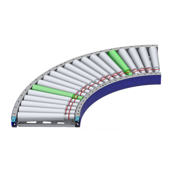
The model shown in Figure 1 contains a dual zone card. These can be used to control two zones simultaneously. While this is a standard configuration, another common configuration is one zone per card. Depending on the RLCDC model, the MDR may be mounted as shown or may be mounted below the tapered rollers. -
Page 8: Receiving
A mark number is a specific number given to a piece of equipment. A mark number is usually made up of a single product line (RZPDC, RLCDC, BZPDC, etc.) but can contain many bed section lengths. They can range from two inches to hundreds of feet. The mark number is used to help identify where the piece of equipment will go within the system layout. -
Page 9: Skid Documentation
Installation and Maintenance Manual: RLCDC 4.3 Skid Documentation All shipments will contain a Bill of Lading for the delivery company, a skid label, and a skid manifest. Skid labels have the contents of each shipped item located on the skid. Figure 3 shows a sample of a skid label. -
Page 10: Installation
7. Attach any guiderail or miscellaneous accessories. For information on guiderail installation, please reference the “Bastian Solutions Conveyor Side Cover and Guiderail Installation Manual” 8. Check that the height of the infeed and discharge ends are correct per the system layout. If installed properly, the curve should be level. -
Page 11: Maintenance And Operation
Installation and Maintenance Manual: RLCDC 6 Maintenance and Operation The longevity and proper functionality of Bastian Solutions conveyor is based upon standard operating practices and general maintenance of equipment. Setting up a regular maintenance schedule will help to ensure that products comply with the equipment’s warranty. Lockout/Tagout procedures should be implemented before performing any maintenance. -
Page 12: Electrical Service
Installation and Maintenance Manual: RLCDC 6.2.2 Electrical Service All Bastian Solutions’ conveyor DC products operate at either 24V or 48V, nominally. • When performing electrical work on Bastian Solutions conveyor, ensure adherence to all applicable OSHA standards. If adjustment of control card settings is required, refer to the respective technical manual listed in •... -
Page 13: Replacing Rollers
Installation and Maintenance Manual: RLCDC 6.2.3 Replacing Rollers For motor driven rollers (MDRs): 1. Follow the lockout/tagout procedure in place to ensure safety. 2. Remove the side cover from the intended work area. 3. Loosen the MDR nut located on the cable side of the roller. -
Page 14: Figure 5: Mdr Removal-2
Installation and Maintenance Manual: RLCDC Apply linear pressure MDR hex shaft Figure 5: MDR Removal-2 7. Pull the threaded shaft out of the side frame. 8. Pull the MDR away from the bands until the MDR is completely free of the side frames and bands. -
Page 15: Replacing Bands
Installation and Maintenance Manual: RLCDC Figure 6: MDR Removal-3 6.2.4 Replacing Bands 1. Follow the lockout/tagout procedure in place to ensure safety 2. Remove the side cover from the intended work area. 3. If band being replaced is on the outside groove/hub of the roller (shown as band number 2 in Figure 7), the two rollers within the bracket symbols will need to be removed. -
Page 16: Figure 7: O-Ring Band Replacement
Installation and Maintenance Manual: RLCDC 15. Re-insert the hex shafts into the appropriate hex holes. 16. Replace side covers. Figure 7: O-ring Band Replacement Published January 2022 Rev. B Rev. B... -
Page 17: Troubleshooting And Repair
Solutions representative as these are the same techniques used by our field service engineers. To assist in data collection, Bastian Solutions asks that any issues that arise be recorded in a log, with the mark number, a description of the issue, and the steps taken to resolve the issue. -
Page 18: Standard Spare Parts
Installation and Maintenance Manual: RLCDC 8 Standard Spare Parts Figure 8: RLCDC Standard Spare Parts Exploded View Table 3: RLCDC Standard Spare Parts Table REF. NO. DESCRIPTION COMMON CONFIGURATIONS ROLLERS 2 GROOVE - TAPERED BANDS CURVE O-RING 2 GROOVE – TAPERED INTERROLL EC100 2 GROOVE –... - Page 19 All rights reserved. This document contains information considered proprietary to Bastian Solutions. It may not be duplicated, used, or disclosed without written permission from Bastian Solutions. It may not be used in whole or in part for any purpose other than its intended purpose as an operation, installation, and maintenance manual for the product or products described herein.
Need help?
Do you have a question about the RLCDC and is the answer not in the manual?
Questions and answers