Table of Contents
Advertisement
Quick Links
Advertisement
Table of Contents

Summary of Contents for MOS OPT100
- Page 1 INSTRUCTION MANUAL Oxygen Monitor OPT100...
-
Page 2: Specifications
2. Specifications Housing ABS Plastic Finishing Electrostatic Epoxy Paint Electrical Connection Terminal Board Cable Inlet Racor 1/2" ( 3 x ) Wall Mounted Installation IP Protection IP65 Power 3.5 VA Weight 1.2 Kg Power Supply 90 ~ 240 VAC or 24V DC 5 ~ 40ºC Operating Temperature Humidity 20 ~ 80 % Display 7 Segment Red Measuring Range 0 100% O Precision Accuracy 0.02 % full scale Operating Temperature 5 40 ºC Auto Temperature Compensation 40 ºC Measuring System Clark Polarographic Cell Sampling Time 20 sec. -
Page 3: Mechanical Dimensions
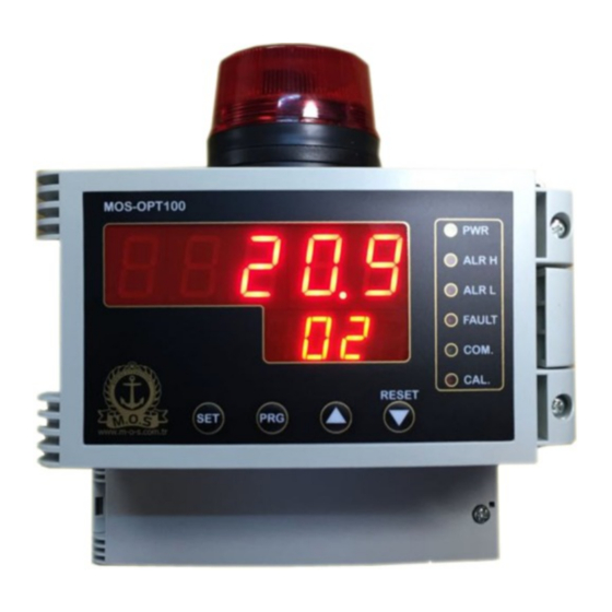
3. Mechanical Dimensions 198 mm 191 mm Oxygen value as % Sensor inlet should be covered for dust and Led display particle penetration during installation. Location should be selected carefully to Keypad. For adjustment and parameter exchange. prevent any direct air flow to the Monitor Siren and flasher from other machinery and / or ventilation. Oxygen Sensor Do not install the unit nearby any heat source. Cable Inlets Cable Inlet Part Cover 1. Electrical connections should be started after finishing the installation. Monitor can easily be connected to the wall with installation fittings that are inside the package. After deciding proper location, you can drill the wall. Monitor will be installed and screwed accordingly. -
Page 4: Electrical Installation
4. Electrical Installation No Connection + Oxygen Sensor Inlet (Red) Oxygen Sensor Inlet (Black) No Connection RS485 A (ModBus RTU) RS485 B (ModBus RTU) + Analog Output 420 mA Analog Output 420 mA N.O. ALARM HIGH C ALARM HIGH Relay Out N.C. ALARM HIGH N.O. ALARM LOW C ALARM LOW Relay Out N.C. ALARM LOW 500mA 9 10 11 12 13 14 Power Supply 200mA 90 240V AC or 24V DC connection. 1 2 3 4 5 6 7 8 Warning: Please connect either AC or DC Power to the unit 90 240 V AC 24 V DC Electric connections can be carried out during installation. Power should be turned on after finishing the installation completely. ... -
Page 5: Parameter Setting
5. Parameter Setting OPT100, shows O2 measurement value at normal Operation mode. High O2 alarm value can be set ALRH With parameter. Press button. aLrH Adjust HIGH Alarm value with up and down buttons. You can set it in between 5.0 to 30.00. Press button. ALRL Low O2 alarm value can be set with aLrL parameter. Adjust LOW Alarm value with up and down buttons. You can set it in between 5.0 to 30.00. Press button. After adjustments OPT100 return its normal operation mode. -
Page 6: Sensor Calibration
6. Sensor Calibration Sensor calibration can be applied to a new sensor or an existing one with shifted measurement. Under this condition O2 sensor should be calibrated via OPT100 panel to read out correct O2 level. Sensor output decreases to 70% when its lifetime expires. You can easily recognize this condition with very low and unlogical O2 value around 5% to 10%. Calibration doesn’t correct this case and sensor should be exchanged for correct measurement. Normally O2 sensor measure 20,9% O2 in regular ambient condition. If you read different value follow below mentioned steps; 1. Connect calibration fitting into N2 bottle (99,9% N2) with pneumatic hose. 2. Connect calibration fitting into the O2 sensor via installing into the sensor inlet. 3. Open the N2 bottle valve and supply gas to the sensor. 4. Check O2 value drop from OPT100 display. O2 value drop will take approximately 30 seconds. O2 should reach to 0,0. If the value is bigger than 0, Zero calibration should be carried out. 5. After reaching 0 value close the N2 bottle valve and remove the calibration fitting. 6. O2 value will rise slowly and reach to 20,9 approximately in 1 minute. If the value is different than 20,9 SPAN calibration should be carried out with SPAN parameter. Calibration Accessory Follow up SPAN calibration instructions. Nitrogen (N2) Tube %99.9... - Page 7 7. Span ve Z ero P aram eter A djustm ent Normal Operation Screen Press button for 5 seconds. OPT100 will request safety code. Write 122 with arrow buttons and press SET. Code CaLb Calibration adjustment parameter will be opened. 6rvb ZERO parameter screen will be opened. Decrease the value to 0,0 with arrow Zero button via pressing it continuously. Be sure that Calibration fitting is connected to the sensor and N2 bottle valve is opened with 99,9% N2 gas supply to the sensor. After reaching to 0 value press SET button and stop the gas supply. SPAN parameter shows ambient O2 value. Apply calibration for values different span than 20,9 (lower or higher) Reach 20,9 value by pressing arrow buttons. After reaching 20,9 value do not touch any button. OPT100 will return to normal operation mode by itself in 30 seconds. Normal Operation Screen.
- Page 8 8. Oxygen Sensor Exchange / Repair SENSOR EXCHANGE: Sensor is packed with its cover to keep its electrolyte in passive mode. Open the sensor cover just before 24 hours of installation and keep it at ambient condition that will operate. Passive electrolyte will get active with this way and start to measure correctly after installation into the OPT100 panel. Do not forget to note sensor installation date onto the panel. Please check SENSOR CALIBRATION part for new sensor calibration. ②⑦①③ Sensor date code: Week Year (2013) SENSOR REPAIR: Do not open the sensor for any repair attempt. There isn’t any repairable part inside the sensor and it will be damaged permanently. Inner Electrolyte can also create severe irritation on skin.
-
Page 9: Trouble Shotting Guide
Trouble Shotting Guide O2 level is too low: Sensor inlet can be blocked. Sensor lifetime can be expired. Please check installation date of the sensor. O2 Level stay constant and freezed. Blow air into the sensor inlet slowly for 5 to 10 seconds and observe value alteration. Check terminal board connections of the sensor. Remove one of the terminal board connection of the sensor and check panel screen for alteration. If screen value is exchanged than sensor is damaged or expired. If value stay constant consult supplier. Panel screen isn’t working. Please check the cable and its socket in between front panel and mainboard and be sure its properly connected. Open the panel cover and check aft terminal board connections. Check the power supply. If O2 level and green POWER light aren’t on, check the fuses inside the panel.
Need help?
Do you have a question about the OPT100 and is the answer not in the manual?
Questions and answers