Advertisement
CPR Aquatic, INC•P.O. Box 1111•3749 West End Road, Arcata, CA 95521
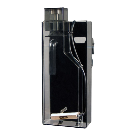
As many hobbyists venture into the world of reef keeping, a common goal among most is to keep the filtration
system as simple as possible. One of the most important components to filtration is the removal of compounds
which could eventually break down into ammonia and nitrite. The AeroForce
highly efficient protein skimmer for a reef system. The AeroForce
Maintenance easier and for sturdier construction. Requiring no supplemental plumbing, the AeroForce
hangs on the back of the tank and can be installed in a few short minutes.
TM
To place your AeroForce
1) Carefully remove all packaging and inspect the unit for damaged or missing parts. You should have:
(1) Outer acrylic body
(1) Inner protein skimmer body
(1) Pico400 (feed pump)
(1) MA400 air pump
(2) Wooden air diffusers
(1) Collection cup assembly with "O" ring and lid
(1) Support pin
If any items are damaged or missing, please contact your dealer immediately.
2) Rinse inside of the AeroForce
3) Remove inner body from outer body. The unit should come with the wooden air duiffusers installed on the inside
of the unit. Secure the two airlines coming out of the air diffusers to the air pump outlets and place the air
pump in a secure location. Insert the airline into the black airline clip on the side of the unit.
4) Slide the inner skimmer body into the outer body. The inlet pipe parts 1 and 2 should line up once the two bodies
are together (see page 4).
5) Attach the Pico4 (5) to the inlet part 2.
TM
6) Hang the AeroForce
TM
AeroForce
AP so that it is parallel to the back of the tank. Insert the support pin into the desired position
first, and then adjust the screws accordingly.
7) Clean the collection cup (1) including the throat of the funnel in hot water. This will cause the skimmer to begin
collecting waste faster. Do not use any detergents on the collection cup. Insert cup inside protein skimmer
section with O-ring placed around the outside. The o-ring acts as a support for the cup to rest on top of the
TM
AeroForce
AP body. This is not intended to form a seal inside the body.
CPR Technical Support (707) 826-9636 • FAX (707) 826-9623
AeroForce
TM
AP into operation:
TM
AP with warm water. (optional, but recommended)
AP on your tank. Use the adjustment screws (7) and support pin (6) to position the
www.cprusa.com • cpr@cprusa.com
AP (Air Pump)
TM
AP is designed to provide a simple yet
TM
AP employs a new dual-body chamber to make
TM
simply
Advertisement
Table of Contents

Subscribe to Our Youtube Channel
Related Manuals for CPR AeroForce AP


Summary of Contents for CPR AeroForce AP
- Page 1 CPR Aquatic, INC•P.O. Box 1111•3749 West End Road, Arcata, CA 95521 AeroForce AP (Air Pump) As many hobbyists venture into the world of reef keeping, a common goal among most is to keep the filtration system as simple as possible. One of the most important components to filtration is the removal of compounds which could eventually break down into ammonia and nitrite.
- Page 2 8) Plug in the feed pump (5) first. Once the wooden air diffusers becomes submerged, plug in the air pump (8). Your AeroForce AP is now operational. The base of the collection funnel should be 1/8” below the water surface for optimal performance. Slide the O-ring (2) up or down until the desired skimmate wetness is achieved.
- Page 3 Clean the air diffusers with water and replace, if necessary. Before calling CPR’s Technical Support, please take some time to look over this trouble shooting guide. Most of the problems associated with the performance of the are due to improper maintenance of the pumps.
- Page 4 Diagram A Collection cup (9) Collection cup (1) Support pin (6) Inlet O-Ring (2) (part 2) (around cup) Outlet (8) Inlet (part 1) Pico 400 (5) Inner body (3) Adjustment screws (7) Inner body slides down into the outer body. Ensure that the Inlet (part 1) and Inlet 2 Air Diffusers (4) (part 2) are in line with each...
Need help?
Do you have a question about the AeroForce AP and is the answer not in the manual?
Questions and answers