
Related Manuals for Sauer WP 33 L


Summary of Contents for Sauer WP 33 L
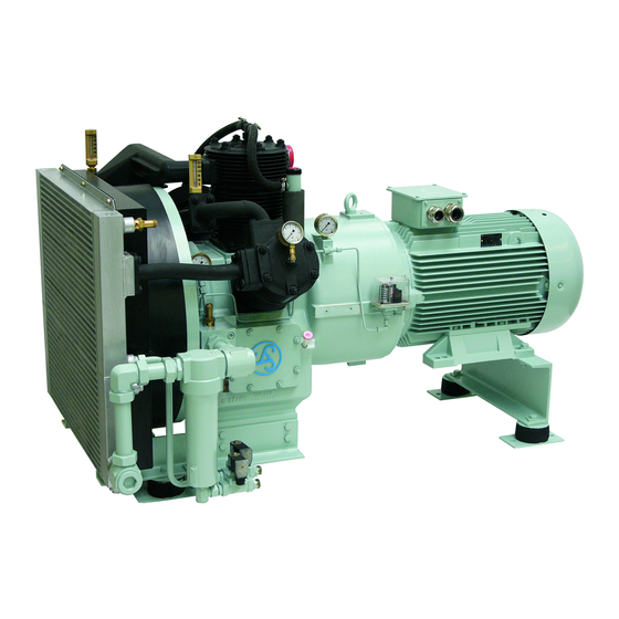
- Page 1 S a u e r C o m p r e s s o r Type: WP 33 L Operator Manual High-pressure Compressor 2 Stages Air-cooled...
- Page 2 WP33L_BA_Titel_en_08.fm Edition: 11 / 2008 Edited by: J.P. Sauer & Sohn Maschinenbau – Technical Documentation...
- Page 3 Sauer compressor Type Approvals Note! On this page only a few examples are shown. FurtherType Ap- provals are available on request.
- Page 4 Genuine Sauer spare parts – certified safety...
-
Page 5: Table Of Contents
Functional description ......... 24 Indicators for the Sauer compressor ......26 Compressor Control System - Indicators and Control . - Page 6 Maintenance ..........50 Maintenance and Service by J.P. SAUER & SOHN ....50 Maintenance safety .
- Page 7 Storage, Preservation - “lay-up“ procedure ..... . 73 Safety when storing and removing ....... 73 Temporary preservation &...
-
Page 8: General
These instructions should always be readily available at the com- pressor installation. Copyright The copyright for these instructions remains with J.P. SAUER & SOHN. These instructions, or parts thereof, shall not be copied, distributed or made available to third parties. Contravention will... -
Page 9: Warrenty And Liability
General 1.3 Warranty and Liability Sauer can no longer cover warranty, be liable for any claims, if a failure is attributed to any of the following: – use of the machine not as specified; – substitution of parts not manufactured or approved by Sauer;... -
Page 10: Type Approval And Genuine Sauer Spare Parts
Table of Contents in these instructions. If spare parts are received without this certificate, there is a risk that these are not genuine Sauer spare parts. In such an istance please contact our Customer Service. -
Page 11: Sauer & Sohn Customer Service
Emergency service (international): +49 172 4 14 63 94 E-Mail: service@sauersohn.de Web: www.sauersohn.de Note! If you have questions regarding your Sauer Compressor, please state Compressor model and serial number (see chapter 11 “Spare Parts and Accessories” or nameplate on the compres- sor). -
Page 12: Specific Instructions
1.6 Specific instructions Lists General lists are hyphenated. e. g.: Compressor cooling consists of – fan wheel, – fan wheel cage, and – cooler assembly. Instructions Individual instructions or multiple instructions requiring action but where the sequence is of no importance are normally denoted by a bullet-point. -
Page 13: Safety
Safety Safety 2.1 Conditions of use This Sauer Compressor must be used for the compression of air. The Sauer Compressor must not be used at ambient temperatu- res below +5 °C. Any other use not as specified, requires the ex- plicit consent in writing from J.P. -
Page 14: Safety Information - Warning & Caution
2.3 Safety information - Warning & Caution The safety information in these instructions is presented as ’high’ risk and ’lower’ risk, as follows: Warning - Danger! High risk. Ignoring this safety information can cause personal injury, or death, and significant equipment damage. Caution - Note! Less risk. -
Page 15: Safety Warnings On The Machine
Safety labeling affixed to the machine must not be altered or re- moved. Replace damaged or lost safety labels immediately with an approved replacement. Sauer compressor models with an EC Manufacturer's Declarati- on or EC Declaration of Conformity are marked with the following safety labels:... -
Page 16: Safety And Protection Devices
The fusible plug can only be used once. If it blows, it needs to be replaced with a new one. As an alternative to the fusible plug, the Sauer compressor can be fitted with a temperature sensor to protect against a compres- sor cooling failure. -
Page 17: Noise Protection
(see Chapter 4). The Sauer compressor can be arranged with a sound-dampening enclosure to reduce the noise. This sound-dampening enclosure is available as optional accessory from J.P. SAUER & SOHN. Danger! When the compressor is operated without sound-dampening en- closure, hearing protection should be worn when working near to the compressor. -
Page 18: Personal Safety
2.8 Personal safety Only personnel authorised by J.P. SAUER & SOHN are permitted to Service the Sauer Compressor! Before commencing work they must have read and understood the instructions in the Manual, and must be familiar with all safety devices and safety regulati- ons. -
Page 19: Personal Protection
Safety 2.9 Personal protection The user should provide personal protection (e.g. hearing protec- tion, safety boots, etc.) for the operator, or Service engineer car- rying out any work on the Sauer compressor. -
Page 20: Design And Function
Design and Function 3.1 Overview Note! Details of parts and spare parts can be found in the spare parts catalogue. - Page 21 Design and Function Item Designation Cylinder 1 stage Cylinder 2 stage Cooler Safety valve 1 stage Safety valve 2 stage Oil / water separator Drain valve Fusible plug Oil dipstick Motor...
- Page 22 Vertical sectional view Item Designation Cooler 1 stage Cooler 2 stage Fan / Flywheel Connecting rod 1 stage Connecting rod 2 stage Flexible coupling, compressor half coupling Bell-housing Crankshaft Bearing bracket...
- Page 23 Design and Function Horizontal sectional view Item Designation Cylinder with head and valve 1 stage Air filter Piston 1 stage Connecting rod 1 stage Cylinder with head and valve 2 stage Piston 2 stage Connecting rod 2 stage Crankcase Oil dipper rod Crankcase vent...
-
Page 24: Functional Description
3.2 Functional description Drive The Sauer Compressor is driven by an electric motor flange- mounted to the crankcase bell-housing. The power is transmitted by means of a flexible coupling. The fan on the crankshaft is part of a fan-flywheel system. - Page 25 The condensate is drained through a drain line. As a drain valve, a solenoid valve is installed in the drain line. The drain valve is draining/ open as long as the Sauer compressor is switched off. The drain pressure relief valve should close some seconds after starting, to allow the Sau- er compressor to run-up against pressure.
-
Page 26: Indicators For The Sauer Compressor
3.3 Indicators for the Sauer compressor Item Designation Display Pressure gauge Compressed air pressure after the 2 stage... -
Page 27: Compressor Control System - Indicators And Control
3.4 Compressor Control System - Indicators and Control Note! If the Compressor Control system is supplied by J.P. SAUER & SOHN read the documentation supplied. On the front of the Compressor Control, the following indicators and control features can be found:... -
Page 28: Technical Specification
Technical Specification 4.1 Specification data Description Data Compressor type WP 33 L Number of cylinders Number of compression stages 100 mm Cylinder diameter 1 stage 46 mm Cylinder diameter 2 stage Piston stroke 42 mm Maximum speed 2000 rpm Direction of rotation (when viewed from... - Page 29 Technical Specification Description Data Final pressure sensor (option): Maximum switching current 6 A / 220 V Setting as customer's specification Switch function change-over contact Outlet non-return valve: Actuation pressure ca. 1 bar Sound pressure level max. 87 dB(A) (free field at 1 m) Weight and dimensions see Installation Drawing Note!
-
Page 30: P&I Diagram
4.2 P&I Diagram Air outlet Air intake atm. oil / water outlet Air intake filter Solenoid valve Motor Inter- Safety valve cooler Compressor stage Non-return valve Separator Final pressure switch Pressure gauge... - Page 31 Technical Specification Item Designation Motor Safety valve 1 stage Safety valve 2 stage Compressor 1 stage Compressor 2 stage Cooler 1 stage Cooler 2 stage Pressure gauge 2 stage Oil/water separator Solenoid valve (drain valve) Air intake filter Non-return valve Final pressure switch...
-
Page 32: Transport And Installation
• Immediately on receipt of the Sauer Compressor it should be checked for completeness and any damage. • The transport company and J.P. SAUER & SOHN must be no- tified immediately of any damage to the packing or the ma- chine. -
Page 33: Storage Before Installation
Transport and Installation 5.2 Storage before Installation If the Sauer Compressor has to be stored before installation, do not unpack, and store in the following conditions: – temperature: +5 to +40°C; – relative humidity 30 … 95%, non-condensing; – dry area, under a roof and protected against the weather;... -
Page 34: Installation
Note! If in doubt regarding the suitability of the intended place of instal- lation, please contact J.P. SAUER & SOHN. Sauer can provide help with the design of a ventilation, system if required. For proper installation observe the installation instructions and the following. - Page 35 – Do not install several compressors one after the other, to pre- vent one compressor from taking in the warmed-up cooling air of another compressor. Note! J.P. SAUER & SOHN would be pleased to advise on the instal- lation of the compressors.
- Page 36 10 Hz range. This helps to avoid any risk that the stan- dard resilient-mount being excited by a resonant frequency. 1. Check that there are no excitation ’foundation’ vibrations in the 10 Hz range. 2. If in doubt, contact J.P. SAUER & SOHN for advice on a pos- sible alternative resilient-mount.
-
Page 37: Connecting The Compressor
The crankcase vent is protected with an insulating hose. Do not take away this insulating material. Pipelines The compressed air outlet and the oil / water lines for the Sauer compressor must be flexibly connected to any final customer sys- tem piping. - Page 38 Note! Accumulated ’condensate’ contains oil. It may only be disposed of in compliance with applicable legal regulations. J.P. SAUER & SOHN offers oill / water preparation systems for separating the oil from the condensate. Note! We recommend to connect the compressor’s drainage separa- tely.
- Page 39 Transport and Installation Installation The illustration below shows the connections and fittings for the operation of a typical Sauer compressor. Item Description Type Function Drive motor AC motor Compressor drive Drain valve Solenoid valve Start relief and drainage Final pressure...
-
Page 40: Stop/Start Pressure Switch Setting(S)
5.5 Stop/Start pressure switch setting(s) Note! Any final pressure switch should be connected directly to the compressed gas storage vessel to ensure a proper compressor operation. Keep in mind the pressure drop between the compressor and the compressed gas storage for setting the maximum pressure. The safety valve of the final stage will blow if the set value of pressure is too high. -
Page 41: Filling With Oil
Transport and Installation 5.6 Filling with oil Note! Unless otherwise ordered, Sauer compressors are delivered without oil. Oil filler Dipstick Danger The compressor's crankcase oil sump must be filled with oil be- fore initial operation! Use recommended lubricating oil (see Chapter 10: “Lubricant Table”). -
Page 42: Installation Checks And Before The Initial Start
5.7 Installation checks before the initial start – Verify electrical connection corresponds with the nameplate? – Check all air connections are propperly installed. Pay special attention to the compressed air outlet. – Are drain lines properly connected? See section “Drainage”. –... -
Page 43: Operation
Operation 6.1 Safe operation Danger! Only authorised persons are permitted put into operation and operate the Sauer Compressor! Danger! Turn on and start the compressor only if – it has been checked for proper working condition; – all tools and foreign objects are removed from the machine. -
Page 44: Operation Modes
6.2 Operation modes When the power supply to the Sauer compressor is turned on, it can be started with one of the following two operational modes: – Normal operation mode “Manual“: The compressor starts and keeps running until it is stopped or turned off with either the operation mode selector or the main switch. -
Page 45: Initial Operation
7. If necessary, correct any faults. See also Chapter 7 “Trouble- shooting“. 8. Complete the start up journal and send it to J.P. SAUER & SOHN service department. The start up journal is in the Ap- pendix of this Manual. -
Page 46: Routine Operation
6.4 Routine operation Cleaning • Keep compressor area clean. • Keep indicators and control elements clean. Checks • Inspect connections, pipes and electric cables for damage. • Check the oil level once a week before starting, top up, if nec- essary. -
Page 47: Troubleshouting Guide
Control Panel (fault = RED). • The following information tabulated below, provides help to correct any fault. If the fault cannot be corrected, please contact J.P. SAUER & SOHN customer service. The fault description journal is in the appendix of this manual.. - Page 48 Fault Probable cause Remedy Pressure exceeds set stage valve malfunction. Check 2 stage valve, replace if nec- pressure (8 bar) essary. Gasket between inlet and out- Replace gasket. let at the 2 stage is faulty. Pressure below set Safety valve is faulty. Replace the safety valve.
- Page 49 Troubleshooting guide Fault Probable cause Remedy Abnormal compressor Connecting rod bearing faulty. Check connecting rod bearing, replace noise. (noise when off-load). if necessary. Check oil supply. Gudgeon pin bearing faulty. Check gudgeon pin bearing, replace if necessary. Crankshaft bearing faulty. Check crank shaft bearing, replace if necessary.
-
Page 50: Maintenance
Maintenance 8.1 Maintenance and Service by J.P. SAUER & SOHN The J.P. SAUER & SOHN customer service offers differing main- tenance services – e.g. full maintenance or valve replacement service. Please contact: J.P. SAUER & SOHN Maschinenbau GmbH Customer Service P.O. -
Page 51: Maintenance Safety
2. Post sign “Caution Maintenance Work!” at the power supply. Danger! Only authorised persons are permitted to Service and make ad- justments to the Sauer Compressor! Danger! Risk of injury from hot surfaces! Let compressor cool down after turning OFF. -
Page 52: Maintenance Schedule
After 4,000 operating hours the maintenance schedule begins all over again. The major overhaul after 8,000 operating hours shall be carried out by personnel authorised by Sauer. Instructions for • Use the maintenance schedule as a master template or copy... - Page 53 Maintenance Maintenance Schedule No.: Compressor type: Maintenance schedule beginning: Type series after commissioning Compressor number: after major overhaul Factory No.: Date: Year of construction: Operating hours: Date of Commissioning: Interval [Operating hours] periodically Maintenance work Checking screwed connections ...
-
Page 54: Table Of Tightening Torques
Note! Always check the compressor after 50 hours following any maintenance work. Check all screws affected by the mainte- nance work to see if they are tight. 8.4 Table of tightening torques Bolt(s) / Screw(s) Tightening torque 38 Nm Cylinder head screws 1 stage 38 Nm Cylinder head screws 2... -
Page 55: Oil Change
Maintenance 8.5 Oil change Note! Only use oil as recommended in the Lubricant Table (see Chap- ter 10). Oil filler Dipstick Oil drain plug 1. Put oil catchpan of sufficient size under the Sump oil drain as- sembly (sufficient capacity to hold the complete oil fill, see Chapter 4 “Technical Specification”). -
Page 56: Checking Screw Connections
8.6 Checking screw connections Check all unions and screw connections for tightness, re-tighten as necessary: – cooler and gas lines; – unions for pipe lines and flexible hose-lines; – cylinder heads; – cylinders; – electric motor and bell-housing flange; – monitoring and protective sensors; –... -
Page 57: Air Intake Filter Cartridge Cleaning
Maintenance 8.7 Air Intake filter cartridge cleaning air filter clamp 1. Loosen clamp and remove air filter. 2. Unfasten the clips at the air filter and remove air filter cap. 3. Wipe out the cover with a lint-free cloth. 4. The air filter is part of the base of the air filter cage. Wash out the air filter with an oil dissolving fluid (e.g. -
Page 58: Checking Valves
Repair by maintenance and operating personnel requires specialist knowledge, which may not be readily available. In such a case J.P. SAUER & SOHN can offer a valve replacement service; please contact the Sauer service department. Note! Install all valves with new gaskets and seals. - Page 59 Maintenance Valve installation 5. Fit reed (lamellar) valve and cylinder head of the 1 stage, use a new cylinder head gasket between valve and cylinder head. stage Lamellar valve Cylinder head gasket Note! Do not reuse used seals under any circumstances. Doing so leads to leakage within a short time.
- Page 60 stage Lamellar valve Cylinder head gasket 8. Fit inner gasket ring between the pins. 9. Observe the tightening torques of the cylinder head nuts: 38 10. Attach all unions and hose lines to the cylinder heads.
-
Page 61: Checking The Piston Rings
Maintenance 8.9 Checking the piston rings 1. Remove cylinder heads and valves as described in Chapter 8.8 “Checking valves”. 2. Remove cylinder base nuts and pull off the cylinder carefully. Hold the piston while the cylinder comes off. Note! If the piston is not held, when pulling the cylinder off, it will fall against the crankcase. - Page 62 stage stage 8. The piston ring gaps should be staggered. 9. Fit a new cylinder base gasket for each cylinder. stage stage cylinder base gasket 10. Push the piston up to the piston pin bore into the respective cylinder. Fit the cylinder together with the piston. 11.
-
Page 63: Replacing Gudgeon Pins / Bearings
Maintenance 8.10 Replacing gudgeon pins / bearings 1. Remove cylinder heads and valves as described in Chapter 8.8 “Checking the valves”. 2. Remove cylinders and pistons as described in Chapter 8.9, “Checking the piston rings”. Note! If the connecting rods are not held, when pulling off, they will fall against the crankcase. -
Page 64: Replacing Valves
stage stage motor 8. Fit pistons and cylinders as described in section 8.9, “Che- cking the piston rings”. 9. Fit cylinder heads and valves as described in section 8.8, “Checking the valves”. 8.11 Replacing valves Remove and install valves as detailed in section 8.8 “Checking valves”. -
Page 65: Checking Pistons And Cylinders
Maintenance 8.12 Checking pistons and cylinders 1. Remove cylinder heads and valves as described in section 8.8 “Checking the valves”. 2. Remove cylinders and pistons as described in section 8.9, “Checking the piston rings”. 3. Check cylinders and pistons for scoring marks and excessive wear. -
Page 66: Checking The Drive Bearings
8.13 Checking the drive bearings 1. Remove cylinder heads and valves as described in Chapter 8.8 “Checking the valves”. 2. Remove cylinders and pistons as described in Chapter 8.9 "Checking the piston rings". connecting rod 3. Check crankshaft bearings (big end bearing), replace if worn. If necessary use new shaft seal. - Page 67 Maintenance bearing bracket crankshaft crankshaft bearing 7. Take the crankshaft out. crankshaft bearing 8. Check crankshaft bearings, replace if worn. If necessary use new shaft seal. Note! Only replace the crankshaft lip seal if the bearing housing and crankshaft are removed! crankcase bearing bracket shaft seal...
- Page 68 12. Fit motor with flange and coupling. 13. Fit pistons and cylinders as described in Chapter 8.9 “Che- cking the piston rings”. 14. Fit cylinder heads and valves as described in Chapter 8.8 “Checking valves”.
-
Page 69: Replacing The Connecting Rod
Maintenance 8.14 Replacing the connecting rod 1. Remove the connecting rods as described in Chapter 8.10 “Replacing gudgeon pins / bearings“. Note! When replacing a connection rod, the gudgeon pin of the corresponding stage must also be replaced. 2. Place the well oiled connecting rods onto the crankshaft. Make sure the connecting rods are in the correct position on the crankshaft (see illustration). -
Page 70: Checking The Coupling And Replacing The Coupling Insert
8.15 Checking the coupling and replacing the coupling insert Inspection / Dis- 1. Shut down the compressor and secure it against restarting.. mantling the 2. Support the compressor under the bell housing. coupling insert 3. Unscrew fixing screws of the motor. 4. -
Page 71: Checking The Oil/Water Separator
Maintenance 8.16 Checking the oil/water separator Item Designation Separator, separator housing Safety valve 2 stage Reducing stub 1. Kompressor ausser Betrieb setzen und gegen Wiederanlauf sichern. 2. Angebaute Leitungen und Schläuche demontieren. 3. Remove safety valve 2 stage. 4. Remove separator housing from the crankcase. 5. -
Page 72: Checking The Safety Valves
8.17 Checking the safety valves Danger! There is risk of injury from escaping air. Therefore keep your head away from the safety valve. Note! The testing operation must take place quickly and must not be repeated. 1. Turn on the system and start up the compressor unit until it has reached final pressure. -
Page 73: Storage, Preservation - "Lay-Up" Procedure
Storage, Preservation – “lay-up” procedure Storage, Preservation – “lay-up” procedure 9.1 Safety when storing and removing Danger! The compressor shall only be removed and “laid up” by trained specialists of the owner. These specialists must be familiar with the protection devices and regulations before starting the work. Any work on the electrical installation must be carried out by qualified electricians only. -
Page 74: Temporary Preservation & Storage
If idle, every 4 weeks perform a test run for at least 30 minutes. Additional corrosion prevention measures are not required. When the Sauer compressor is to be layed-up for more than 12 weeks, preservation with a flushing or preservation oil is recom- mended. - Page 75 Storage, Preservation – “lay-up” procedure preservation oil stage 9. Wait until oil mist comes out of the final pressure line. 10. Stop compressor. 11. Install the air intake filter and the safety valve. Use new O-ring for the safety valve. 12.
-
Page 76: Removing
9.3 Removing Removing 1. Turn compressor off and disconnect from power supply. 2. Make sure by reading the gas pressure display that the com- pressor is completely relieved of pressure. 3. Disconnect mains supply cables. 4. Remove oil and lubricants for safe disposal. 5. -
Page 77: Lubricant Table
The lubricant table applies to all Sauer Compressors intended for the compression of air. The lubricant table does not apply to – Sauer Compressors for the compression of inert, noble or haz- ardous gases; – temperature ranges outside of +5 … +55°C. -
Page 78: Lubricating Oils
10.1 Lubricating oils The approved list of mineral oils can be used in Sauer compres- sors; as a standard for industrial applications, the mineral oil Shell Corena P 100 is used in Sauer compressors. Brand Product name Class Agip Diesel Gamma 30... -
Page 79: Preservation Oils
O - 278 VDL-120 NATO classified OMD 113 VDL-100 10.2 Preservation oils Mobilarma 524 is recommended to be used as preservation oil for Sauer compressors. Alternatively, the following preservation oils can be recommend- Brand Product name Agip Rustica C SAE 30 ARAL... -
Page 80: Spare Parts And Accessories
They conform to the latest tech- nical developments. In addition to the genuine Sauer spare parts, our delivery pro- gram comprises a large number of accessories for your Sauer Compressor and special components to complete your air sys- tem, such as: –... - Page 81 CD-ROM. An order form can be complet- ed, printed out and sent immediately. To do so, you need the main specification of your Sauer Kompressors from the table below. If the data has not yet been entered, it can be found on the nameplate affixed to the crank- case.
-
Page 82: Annex
12 Annex This Annex to the operating instructions contains – the blank for the start-up journal; – the blank for notification of claim and return of goods; – documentation supplied by outside vendors; – data sheets. - Page 83 Operatiors have received instruction and are familar with safety and maintenance required. The maintenance instructions are ready available. The operating company has been advised to only genuine SAUER & SOHN spare parts. Notes / Faults: The system has been accepted by the operating...
- Page 84 J.P. SAUER & SOHN Return of goods Maschinenbau GmbH Notification of claim Brauner Berg 15 - 24159 Kiel Phone: +49 - 431- 39 40 - 0 Fax: +49 - 431- 39 40 - 89 Date: e-mail: service@sauersohn.de Applicant:...
- Page 85 S a u e r C o m p r e s s o r Type: WP 33 L Spare Parts List...
- Page 86 WP33L_ET_Titel_en_08.fm Edition: 11 / 2008 Edited by: J.P. Sauer & Sohn Maschinenbau – Technical Documentation...
- Page 87 Spare Parts List 060 465 / 065 567 Sauer Compressor WP33L-100 Page Ref. No. Module 060 465 Sauer Compressor WP33L-100 (Four-point Mounting) ............065 567 Sauer Compressor WP33L-100 (Three-point Mounting) ............060 315 Compressor WP33L-100 ............. 060 316 Crankcase................061 383 Dipstick ................
- Page 88 Note: Explainations of the assemblies in Chapter 3 “Design and Func- tion“ of the operator manual. E - 4...
- Page 89 Spare Parts List E - 5...
- Page 90 060 465 Sauer Compressor WP33L-100 8, 18 14, 15, 16 9, 10 stage stage E - 6...
-
Page 91: Sauer Compressor Wp33L-100
Spare Parts List 060 465 Sauer Compressor WP33L-100 Item Ref. No. Description Qty. 060 315 Compressor WP33L-100 060 354 Automatic drainage system 060 439 Compressor base 060 441 Spacer 035 318 Motor half coupling 033 637 Coupling flexible insert AC motor... - Page 92 065 567 Sauer Compressor WP33L-100 8, 18 14, 15, 16 9, 10 stage stage E - 8...
- Page 93 Spare Parts List 065 567 Sauer Compressor WP33L-100 Item Ref. No. Description Qty. 060 315 Compressor WP33L-100 060 354 Automatic drainage system 065 569 Compressor base 060 441 Spacer 035 318 Motor half coupling 033 637 Coupling flexible insert AC motor...
- Page 94 060 315 Compressor WP33L-100 1, 19, 20 E - 10...
- Page 95 Spare Parts List 060 315 Compressor WP33L-100 stage stage 25, 26 E - 11...
- Page 96 060 315 Compressor WP33L-100 E - 12...
-
Page 97: Crankcase
Spare Parts List 060 315 Compressor WP33L-100 Item Ref. No. Description Qty. 060 316 Crankcase 060 317 Crankshaft 060 280 Connecting rod 1 stage 060 283 Connecting rod 2 stage 034 989 Piston 1 stage 060 319 Piston 2 stage 060 304 Cylinder with head and valve 1 stage... - Page 98 060 316 Crankcase 3, 23 stage stage 38 Nm 38 Nm 2, 18, 19, 23 14, 21 E - 14...
- Page 99 Spare Parts List 060 316 Crankcase Item Ref. No. Description Qty. 060 376 Ventilation stub 054 816 Stud bolt 054 817 Stud bolt 060 404 Crankcase 060 409 Bearing bracket 061 383 Dipstick 060 425 Clamp 060 448 Cylinder base gasket 060 449 Cylinder base gasket 031 103...
- Page 100 061 383 Dipstick E - 16...
- Page 101 Spare Parts List 061 383 Dipstick Item Ref. No. Description Qty. 035 605 Dipstick 035 528 O-ring E - 17...
- Page 102 060 317 Crankshaft E - 18...
- Page 103 Spare Parts List 060 317 Crankshaft Item Ref. No. Description Qty. 060 325 Crankshaft 050 510 Fan / flywheel 035 026 Cylindrical roller bearing 001 096 Hexagon nut 001 691 Lock plate 001 984 001 981 E - 19...
- Page 104 060 280 Connecting rod 1 stage 4, 7 50 Nm E - 20...
- Page 105 Spare Parts List 060 280 Connecting rod 1 stage Item Ref. No. Description Qty. 060 274 Connecting rod 050 519 Small end bearing 050 520 Big end bearing 050 459 Connecting rod screw 032 117 Gudgeon pin Connecting rod screw 050 459 is part of unmachined part Connecting rod. Gudgeon pin 032 117 is part of assembly 034 989.
- Page 106 060 283 Connecting rod 2 stage 4, 7 50 Nm E - 22...
- Page 107 Spare Parts List 060 283 Connecting rod 2 stage Item Ref. No. Description Qty. 060 277 Connecting rod 039 029 Small end bearing 050 520 Big end bearing 050 459 Connecting rod screw 050 585 Gudgeon pin Connecting rod screw 050 459 is part of unmachined part Connecting rod. Gudgeon pin 050 585 is part of assembly 060 319.
- Page 108 034 989 Piston 1 stage E - 24...
- Page 109 Spare Parts List 034 989 Piston 1 stage Item Ref. No. Description Qty. 034 989 Piston 032 117 Gudgeon pin 002 755 Plain ring 002 563 Nose ring 034 988 Oil scraper ring 002 973 Circlip 050 520 Small end bearing Small end bearing 050 520 is part of assembly 060 280.
- Page 110 060 319 Piston 2 stage E - 26...
- Page 111 Spare Parts List 060 319 Piston 2 stage Item Ref. No. Description Qty. 060 355 Piston 050 585 Gudgeon pin 002 662 Plain ring 002 543 Nose ring 002 576 Oil scraper ring 002 973 Circlip 039 029 Small end bearing Small end bearing 039 029 is part of assembly 060 283.
- Page 112 068 628 Cylinder with head and valve 1 stage E - 28...
- Page 113 Spare Parts List 068 628 Cylinder with head and valve 1 stage Item Ref. No. Description Qty. 060 304 Cylinder 1 stage 060 300 Cylinder head 1 stage 030 113 Air filter 060 266 Cylinder head gasket 034 983 Lamellar valve 1 stage E - 29...
- Page 114 068 615 Cylinder with head and valve 2 stage E - 30...
- Page 115 Spare Parts List 068 615 Cylinder with head and valve 2 stage Item Ref. No. Description Qty. 060 302 Cylinder 2 stage 060 267 Cylinder head 2 stage 060 264 Cylinder head gasket 034 984 Lamellar valve 2 stage E - 31...
- Page 116 060 322 Cooler and air piping 9, 16 13, 15 8, 16 8, 16 E - 32...
- Page 117 Spare Parts List 060 322 Cooler and air piping Item Ref. No. Description Qty. 050 545 Cooler 1 stage 060 323 Cooler 2 stage 050 547 Clamp 050 548 Clamp 050 549 Clamp 000 015 Hexagon head screw 012 728 Hexagon head screw 004 993 Fitting...
- Page 118 060 328 Crankcase vent 5, 6 060 328 stage E - 34...
- Page 119 Spare Parts List 060 328 Crankcase vent Item Ref. No. Description Qty. 035 007 Low pressure hose 008 646 Pipe 035 254 Hose clip 006 205 Fitting 005 001 Washer E - 35...
- Page 120 030 915 Safety valve 1 stage E - 36...
-
Page 121: Safety Valve 1 St Stage
Spare Parts List 030 915 Safety valve 1 stage Item Ref. No. Description Qty. 030 915 Safety valve 1 stage 005 009 Washer Washer 005 009 is part of assembly 060 312. E - 37... - Page 122 030 752 Safety valve 2 stage E - 38...
-
Page 123: Safety Valve 2 Nd Stage
Spare Parts List 030 752 Safety valve 2 stage Item Ref. No. Description Qty. 030 752 Safety valve 2 stage 005 009 Washer Washer 005 009 is part of assembly 060 312. E - 39... -
Page 124: Air Pressure Piping
060 440 Air pressure piping 4, 6 7, 8 4, 6 5, 10 E - 40... -
Page 125: Separator
Spare Parts List 060 440 Air pressure piping Item Ref. No. Description Qty. 060 312 Separator 060 444 Pipe 006 212 Fitting 006 187 Fitting 005 006 Washer 035 010 Pressure gauge 035 061 Gasket 004 750 Hexagon head screw 035 426 Filter E - 41... - Page 126 060 312 Separator 2, 7 3, 8 4, 6 E - 42...
- Page 127 Spare Parts List 060 312 Separator Item Ref. No. Description Qty. 060 311 Separator housing 060 340 Baffle 060 342 Fusible plug 006 390 Bottom plug 005 029 Washer 005 023 Washer 005 009 Washer 121°C / 250°F E - 43...
- Page 128 035 010 Pressure gauge E - 44...
- Page 129 Spare Parts List 035 010 Pressure gauge Item Ref. No. Description Qty. 035 010 Pressure gauge 035 061 Gasket Gasket 035 061 is part of assembly 060 440. E - 45...
-
Page 130: Automatic Drainage System
060 354 Automatic drainage system E - 46... - Page 131 Spare Parts List 060 354 Automatic drainage system Item Ref. No. Description Qty. 037 680 Solenoid valve 006 455 Stub 006 381 Reducing socket 004 635 Fitting Specify voltage and frequency for order! Solenoid valve ref. No. as customer‘s specification. E - 47...
- Page 132 060 589 Resilient mounts E - 48...
-
Page 133: Hose Line
Spare Parts List 060 589 Resilient mounts Item Ref. No. Description Qty. 061 001 Hose line 035 457 Anti-vibration resilient mount 038 310 High pressure hose 002 031 Hexagon nut 011 130 Non-return valve 038 197 Mounting plate E - 49... - Page 134 065 568 Resilient mounts E - 50...
- Page 135 Spare Parts List 065 568 Resilient mounts Item Ref. No. Description Qty. 061 001 Hose line 035 457 Anti-vibration resilient mount 038 310 High pressure hose 002 031 Hexagon nut 011 130 Non-return valve 038 197 Mounting plate E - 51...
- Page 136 061 001 Hose line E - 52...
- Page 137 Spare Parts List 061 001 Hose line Item Ref. No. Description Qty. 038 309 High pressure hose 004 694 Fitting E - 53...
-
Page 138: Flexible Coupling (For Sauer Compressor 060 465)
Flexible coupling Motor Compressor E - 54... -
Page 139: Flexible Coupling
Spare Parts List Flexible coupling Item Ref. No. Description Qty. 035 316 Compressor half coupling 035 318 Motor half coupling 033 637 Coupling flexible insert Compressor half coupling 035 316 is part of assembly 060 315. Motor half coupling 035 318 is part of assembly 060 465. Coupling flexible insert 033 637 is part of assembly 060 465. - Page 140 Flexible coupling Motor Compressor E - 56...
- Page 141 Spare Parts List Flexible coupling Item Ref. No. Description Qty. 035 316 Compressor half coupling 035 318 Motor half coupling 033 637 Coupling flexible insert Compressor half coupling 035 316 is part of assembly 060 315. Motor half coupling 035 318 is part of assembly 065 567. Coupling flexible insert 033 637 is part of assembly 065 567.
- Page 142 E - 58...
- Page 143 Index Parts List by Ref. No. Page Ref. No. Description Assembly Item 000 015 Hexagon head screw ....... 060 322 000 026 Hexagon head screw ....... 060 316 000 043 Hexagon head screw ....... 060 465 000 043 Hexagon head screw ....... 065 567 000 054 Hexagon head screw .......
- Page 144 Page Ref. No. Description Assembly Item 002 755 Plain ring ..........034 989 002 973 Circlip ............034 989 002 973 Circlip ............060 319 003 113 Locking washer ........060 322 004 408 Name plate rivet ........060 315 004 635 Fitting ............
- Page 145 Index Page Ref. No. Description Assembly Item 008 646 Pipe ............060 328 009 386 AC motor ..........060 465 009 386 AC motor ..........065 567 011 130 Non-return valve ........060 589 011 130 Non-return valve ........065 568 012 728 Hexagon head screw .......
- Page 146 Page Ref. No. Description Assembly Item 035 010 Pressure gauge ........035 010 035 010 Pressure gauge ........060 440 035 026 Cylindrical roller bearing ......060 317 035 032 Stud screw ..........060 316 035 061 Gasket ............. 060 440 035 061 Gasket .............
- Page 147 Index Page Ref. No. Description Assembly Item 050 510 Fan / Flywheel ......... 060 317 050 519 Small end bearing ........060 280 050 520 Big end bearing ........060 280 050 520 Small end bearing ........060 280 050 520 Big end bearing ........
- Page 148 Page Ref. No. Description Assembly Item 060 312 Separator ..........060 440 060 315 Compressor WP33L-100 ......060 465 060 315 Compressor WP33L-100 ......065 567 060 316 Crankcase ..........060 315 060 317 Crankshaft ..........060 315 060 319 060 315 Piston 2 stage ........
- Page 149 Index Page Ref. No. Description Assembly Item 061 383 Dipstick ............ 060 316 065 569 Compressor base ........065 567 E - 65...
- Page 150 Parts List by Description Page Ref. No. Description Assembly Item 009 386 AC motor ..........060 465 009 386 AC motor ..........065 567 030 113 Air filter ............ 068 628 060 440 Air pressure piping ........060 315 035 457 Anti-vibration resilient mount ....
- Page 151 Index Page Ref. No. Description Assembly Item 060 315 Compressor WP33L-100 ......065 567 060 274 Connecting rod ........060 280 060 277 Connecting rod ........060 283 060 280 060 315 Connecting rod 1 stage ......060 283 060 315 Connecting rod 2 stage ......
- Page 152 Page Ref. No. Description Assembly Item 060 302 060 315 Cylinder with head and valve 2 stage ... 035 026 Cylindrical roller bearing ......060 317 035 605 Dipstick ............ 061 383 061 383 Dipstick ............ 060 316 050 510 Fan / Flywheel .........
- Page 153 Index Page Ref. No. Description Assembly Item 000 150 Hexagon head screw ....... 065 567 004 750 Hexagon head screw ....... 060 440 005 247 Hexagon head screw ....... 060 316 012 728 Hexagon head screw ....... 060 322 012 851 Hexagon head screw .......
- Page 154 Page Ref. No. Description Assembly Item 035 318 Motor half coupling ........065 567 035 318 Motor half coupling ........065 567 038 197 Mounting plate ......... 060 589 038 197 Mounting plate ......... 065 568 004 408 Name plate rivet ........060 315 011 130 Non-return valve ........
- Page 155 Index Page Ref. No. Description Assembly Item 034 228 Screw ............060 316 060 312 Separator ..........060 440 060 311 Separator housing ........060 312 001 884 Shaft seal ..........060 316 039 029 Small end bearing ........060 283 039 029 Small end bearing ........
- Page 156 Page Ref. No. Description Assembly Item 005 029 Washer ............ 060 316 E - 72...
Need help?
Do you have a question about the WP 33 L and is the answer not in the manual?
Questions and answers