Table of Contents
Advertisement
Quick Links
Advertisement
Table of Contents

Summary of Contents for Datalogic LGS-N50
- Page 1 LGS-N50 USER MANUAL Navigation LiDAR Preliminary 13-Jan-2021...
- Page 2 Electronic versions of this document may be downloaded from the Datalogic website (www.datalogic.com). If you visit our website and would like to make comments or suggestions about this or other Datalogic pub- lications, please let us know via the "Contact" page.
-
Page 3: Table Of Contents
CONTENTS PREFACE ........................IV About this Manual ......................iv Manual Conventions ........................... iv Technical Support ......................iv Support Through the Website ......................iv Reseller Technical Support ........................ iv DOCUMENT DESCRIPTION................... 1 SAFETY INSTRUCTIONS....................2 Handle laser device properly .................... 2 Handle electrical connection properly ................2 WORKING PRINCIPLES .................... -
Page 4: Preface
TECHNICAL SUPPORT Support Through the Website Datalogic provides several services as well as technical support through its website. Log on to (www.datalogic.com). For quick access, from the home page click on the search icon , and type in the name of the product you’re looking for. -
Page 5: Document Description
CHAPTER 1 DOCUMENT DESCRIPTION In order to maintain the normal performance of the product and prevent damage to the device, please do not try to open the sensor. • Read the description: please read all the safety and operation information before using this product. -
Page 6: Safety Instructions
The power supply connected with the device must comply with the require- ments included in the operation instructions. CAUTION Please connect the reference potential properly when using the device to avoid injury caused by equal potential current. CAUTION LGS-N50 Preliminary 13-Jan-2021... -
Page 7: Working Principles
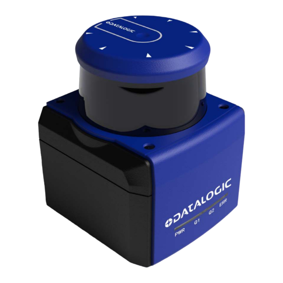
CHAPTER 3 WORKING PRINCIPLES LGS-N50 is a 2D LiDAR sensor developed to meet the needs of Object Localization. The output of this product is point cloud data (Ethernet port). A laser beam emitted from LGS-N50 internal laser diode is projected around LiDAR through a rotating mirror and then returns (the amount of returned laser energy depends on the reflectivity of objects). -
Page 8: Installation And Usage
CHAPTER 4 INSTALLATION AND USAGE MECHANICAL CONNECTION LGS-N50 LiDAR can be installed in two ways: back mounting and base mounting. Back mounting There are four M5 screw holes at the back of the main frame for installation (hole depth: 8mm). -
Page 9: Base Mounting
There are three M5 screw holes at the base of the main frame for installation (hole depth: 8mm). Figure 3 - LGS-N50 Base Mounting interface ELECTRICAL CONNECTION There are three connectors on the back of LGS-N50 for power supply, I/O and 4PIN Ethernet connection respectively as shown below: Figure 4 - LGS-N50 Connection USER MANUAL... -
Page 10: Power Connector
Brown White Blue Black Figure 5 - Power connector I/O connector The pin definitions of the I/O connector are shown below: DEFINITION WIRING COLOR n.c. n.c. n.c. n.c. n.c. n.c. n.c. n.c. Figure 6 - I/O connector LGS-N50 Preliminary 13-Jan-2021... -
Page 11: Ethernet Connector
Figure 7 - Ethernet connector COMMUNICATION The LGS-N50 is connected to the computer through a standard Ethernet RJ-45 connec- tor. The computer IP address must be set prior to establishing communication. Both the LiDAR and the computer IP addresses must be set within the same subnet without con- flicting with each other. - Page 12 INSTALLATION AND USAGE Figure 9 - Computer IP Setting: Step 2 Figure 10 - Computer IP Setting: Step 3 LGS-N50 Preliminary 13-Jan-2021...
-
Page 13: Leds
LEDS LEDs Figure 11 - LGS-N50 LEDs MEANING Shows the status of powered devices (off = no power; on = powered) Shows the status of “out of temperature range” (Tenvironment < Tmin or Tenvironment > Tmax). In such a case, Q1 blinks and the “ERR” LED lights up steadily. -
Page 14: Data Packet Format
CHAPTER 5 DATA PACKET FORMAT Information transmission between LGS-N50 and computer follows UDP/IP standard net- work protocol. The data adapts Little-endian format with low byte at the front and high byte at the end. OVERVIEW Total length of data packet is 1240 bytes, among which the header has 40 bytes, data returned by laser has 1200 bytes. -
Page 15: Definition Of Header
DEFINITION OF HEADER DEFINITION OF HEADER Total length of data packet is 1240 bytes, among which 40 bytes represent the header, and 1200 bytes represent the data returned by laser. OFFSET LENGTH DESCRIPTION ID, it is always 0xFEF0010F Protocol version code, the current code is 0x0200 Distance scale, actual distance = readout data x distance scale (mm) Brand name code. -
Page 16: Data Conversion
5. Multiply by minimum resolution: 1mm 6. Result: 4625mm Calculation of signal strength To calculate the signal strength of LGS-N50, follow the example below: 1. Obtain signal strength value: 0x11 & 0x12 2. Swap high bits and low bits: 0x12 & 0x11 3. -
Page 17: Parameter Configuration
CHAPTER 6 PARAMETER CONFIGURATION WEB SERVER CONFIGURATION LGS-N50 parameters are configured on the web server as follows: • Open the web browser (recommended: Chrome, Firefox, Edge and other stan- dards-compliant browsers). Enter the LiDAR IP address. • The model and version are the product model and firmware version, shown on the upper end of the interface. -
Page 18: Configuration Through Lgs Viewer Pc Software
The required environment for the software to run is as follows: • OS: Windows 7 and above • .NET Framework: 4.5.2 • Pcap: wpcap runtime Network environment The default factory static IP for LiDAR is as follows: • LiDAR IP: 192.168.1.100 • Net mask: 255.255.255.0 LGS-N50 Preliminary 13-Jan-2021... -
Page 19: Lgs Viewer: Windows Firewall
CONFIGURATION THROUGH LGS VIEWER PC SOFTWARE The computer PC receiver sets the static IP as follows: • Host IP: 192.168.1.10 • Net mask: 255.255.255.0 LGS Viewer: Windows Firewall If Windows Firewall is active on the configuration PC, a pop-up window will appear. If no firewall window appears, but an “Unable to connect”... -
Page 20: Using Lgs Viewer
The software will provide scheme level graphics in the Color directory that loads the root at initialization. The graphic size is 256*23 ;*.bmp (24 bit). Record: record a sequence of measure data and save it on a .pcap file. LGS-N50 Preliminary 13-Jan-2021... -
Page 21: Basic Measurement
CONFIGURATION THROUGH LGS VIEWER PC SOFTWARE Basic measurement Go to Tool > ShowTest. This function can be used to measure the distance and intensity of a specified angle. Reset the LiDAR The ResetConfig software program can be used to restore the following settings to fac- tory configuration: •... -
Page 22: Firmware Upgrade
1. Click on the gray box to the right and select the .ldrup firmware file (or drag it to the specified area). 2. Click on the Upgrade button. 3. Open the LiDAR default configuration web page and check that the firmware has been upgraded. LGS-N50 Preliminary 13-Jan-2021... -
Page 23: Technical Parameters
CHAPTER 7 TECHNICAL PARAMETERS GENERAL SPECIFICATIONS Wavelength 905 ± 20 nm Laser class Class 1 Channel Scanning angle 360° Scanning rate 10 to 25 Hz 0.2 to 2 m @ 1.8% Measurement range 0.2 to 15 m @ 10% 0.2 to 50 m @ 80% Ambient light limit >80000 LUX @ sunlight Resolution... - Page 24 IEC 61000-6-2 / IEC 61000-6-3 Laser safety IEC 60825-1 ROHS ✓ Safety requirements UL61010-1 (pending) INDICATORS LED indicator RGB*4 Color Operation indicator Green LED: Power ON Function indicator Red LED: LiDAR fault SOFTWARE Basic software Datalogic LGS Viewer LGS-N50 Preliminary 13-Jan-2021...
-
Page 25: Troubleshooting
• Check power connection • Check whether voltage meets 12 to 32 VDC LiDAR fails to scan If failure persists, contact Datalogic Technical Support. • Check net connection • Check the IP setting of the data receiver • Try to use a third-party data capture tool to check... -
Page 26: Data Packet
APPENDIX A DATA PACKET LGS-N50 Preliminary 13-Jan-2021... -
Page 27: Mechanical Dimensions
APPENDIX B MECHANICAL DIMENSIONS USER MANUAL Preliminary 13-Jan-2021... - Page 28 MECHANICAL DIMENSIONS LGS-N50 Preliminary 13-Jan-2021...
-
Page 29: Example Of Electrical Connection
APPENDIX C EXAMPLE OF ELECTRICAL CONNECTION OUTPUT Q1: USER MANUAL Preliminary 13-Jan-2021... - Page 30 Preliminary 13-Jan-2021...
- Page 31 Preliminary 13-Jan-2021...
- Page 32 © 2021 Datalogic S.p.A. and /or its affiliates • All rights reserved • Without limiting the rights under copyright, no part of this documentation may be reproduced, stored in or introduced into a retrieval system, or transmitted in any form or by any means, or for any purpose, without the express written permission of Datalogic S.p.A.