Advertisement
Quick Links
SERVICE MANUAL
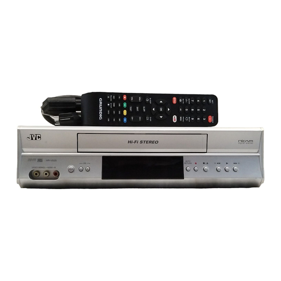
VIDEO CASSETTE RECORDER
2005
12
YD088
/I
AUDIO
MENU
COUNTER
0000
MEMORY
REC
SYSTEM
SP/LP
QUICK-FIND
SEARCH
REM-SHR006E
REMOTO CONTROL
VCR
1
PRECAUTION. . . . . . . . . . . . . . . . . . . . . . . . . . . . . . . . . . . . . . . . . . . . . . . . . . . . . . . . . . . . . . . . . . . . . . . . . 1-3
2
SPECIFIC SERVICE INSTRUCTIONS . . . . . . . . . . . . . . . . . . . . . . . . . . . . . . . . . . . . . . . . . . . . . . . . . . . . . . 1-9
3
DISASSEMBLY . . . . . . . . . . . . . . . . . . . . . . . . . . . . . . . . . . . . . . . . . . . . . . . . . . . . . . . . . . . . . . . . . . . . . . 1-10
4
ADJUSTMENT . . . . . . . . . . . . . . . . . . . . . . . . . . . . . . . . . . . . . . . . . . . . . . . . . . . . . . . . . . . . . . . . . . . . . . . 1-22
5
TROUBLESHOOTING . . . . . . . . . . . . . . . . . . . . . . . . . . . . . . . . . . . . . . . . . . . . . . . . . . . . . . . . . . . . . . . . . 1-31
HR-V525SEF
EJECT
PR
SLOW
PR
VIDEO (MONO) L-AUDIO-R
TABLE OF CONTENTS
COPYRIGHT © 2005 Victor Company of Japan, Limited
Area Suffix
EF -------- French Republic
AUTO
RETURN
HR-V525SEF [V18D1]
No.YD088
2005/12
Advertisement

Related Manuals for JVC HR-V525SEF


Summary of Contents for JVC HR-V525SEF
-
Page 1: Table Of Contents
RETURN VIDEO (MONO) L–AUDIO–R HR-V525SEF [V18D1] TABLE OF CONTENTS PRECAUTION............... . . 1-3 SPECIFIC SERVICE INSTRUCTIONS . - Page 2 SPECIFICATION HR-V525SEF General Specifications Television system SECAM L,L’,PALB/G TV standard Video heads Four-video and Two-audio heads helical scan system Tape width 12.65mm Tape speed SP :23.39 mm/sec. LP:11.70 mm/sec. Tuner channel [SECAM-L] F1~F10 FB~FQ E21~E69 CATV [PAL B/G] E2~E12 E21~E69...
-
Page 3: Precaution
SECTION 1 PRECAUTION IMPORTANT SAFETY PRECAUTIONS (11) Crimp type wire connector The power transformer uses crimp type connectors which 1.1.1 Product Safety Notice connect the power cord and the primary side of the trans- Some electrical and mechanical parts have special safety-relat- former. - Page 4 1.1.3 Safety Check after Servicing Examine the area surrounding the repaired location for damage or deterioration. Observe that screws, parts, and wires have been returned to their original positions. Afterwards, do the fol- Chassis or Secondary Conductor lowing tests and confirm the specified values to verify compli- ance with safety standards.
- Page 5 STANDARD NOTES FOR SERVICING 1.2.2 Pb (Lead) Free Solder When soldering, be sure to use the Pb free solder. 1.2.1 Circuit Board Indications (1) The output pin of the 3 pin Regulator ICs is indicated as 1.2.3 How to Remove / Install Flat Pack-IC shown.
- Page 6 1.2.3.1.3 With Soldering Iron: 1.2.3.1.4 With Iron Wire: (1) Using desoldering braid, remove the solder from all pins of (1) Using desoldering braid, remove the solder from all pins of the flat pack-IC. When you use solder flux which is applied the flat pack-IC.
- Page 7 1.2.3.2 Installation 1.2.4 Instructions for Handling Semi-conductors (1) Using desoldering braid, remove the solder from the foil of Electrostatic breakdown of the semi-conductors may occur due each pin of the flat pack-IC on the CBA so you can install a to a potential difference caused by electrostatic charge during replacement flat pack-IC more easily.
- Page 8 PREPARATION FOR SERVICING 1.3.1 How to Enter the Service Mode 1.3.1.1 About Optical Sensors Caution: An optical sensor system is used for the Tape Start and End Sensors on this equipment. Carefully read and follow the in- structions below. Otherwise the unit may operate erratically. What to do for preparation Insert a tape into the Deck Mechanism Assembly and press the PLAY button.
-
Page 9: Specific Service Instructions
SECTION 2 SPECIFIC SERVICE INSTRUCTIONS This service manual does not describe SPECIFIC SERVICE INSTRUCTIONS. (No.YD088)1-9... -
Page 10: Disassembly
SECTION 3 DISASSEMBLY CABINET DISASSEMBLY INSTRUCTIONS [1] Top Case 3.1.1 Disassembly Flowchart This flowchart indicates the disassembly steps to gain access to [2] Front Assembly item(s) to be serviced. When reassembling, follow the steps in reverse order. Bend, route, and dress the cables as they were originally. - Page 11 (S-1) (S-2) (S-2) (S-1) (S-3) (S-2) (S-3) (S-4) [3]VCR Chassis (S-3) Unit (S-2) [1] Top Case (S-1) Fig.1 (L-2) (L-2) Fig.3 [4] Jack CBA (S-5) [2] Front Desolder Assembly (L-1) Fig.2 Fig.4 (No.YD088)1-11...
- Page 12 [7] Cylinder Shield Cylinder Assembly FE Head (S-7) SW507 LD-SW ACE Head Assembly [6] Main CBA [5] Deck [5] Deck Assembly [8] Jack Board Assembly (L-3) Cam Gear Hole Shaft Hole LD-SW [6] Main CBA [6] Main CBA (S-6) Fig.6 (S-6) TOP VIEW From...
- Page 13 DISASSEMBLY/ASSEMBLY PROCEDURES OF DECK MECHANISM Before following the procedures described below, be sure to remove the deck assembly from the cabinet. (Refer to CABINET DISAS- SEMBLY INSTRUCTIONS.) All the following procedures, including those for adjustment and replacement of parts, should be done in Eject mode; see the positions of [44] and [45] in Fig.1 DM1H on page 1-15.
- Page 14 STEP/ STARTING PART REMOVAL INSTALLATION LOC. No. Fig. No. REMOVE/*UNHOOK/ ADJUSTMENT UNLOCK/RELEASE/ CONDITION UNPLUG/DESOLDER [38] [37] Tension Lever Assembly 1,17 [39] [38] T Lever Holder *(L-10) [40] [40] M Gear (HI) 1,17 (C-6) [41] [15],[40] Sensor Gear (HI) 1,17 (C-7) [42] [36],[40] Reel T...
- Page 15 Top View [44] [45] [49] [46] [14] [13] [11] [15] [38] [10] [12] [37] [36] [43] [32] [41] [31] [40] [42] Fig.1 Bottom View [19] [35] [34] [25] [23] [24] [26] [27] [22] [28] [20] [33] Fig.2 (No.YD088)1-15...
- Page 16 (S-1) (S-1) (L-1) (L-3) (L-2) (S-1A) (P-1) Installation of [3] and [6] First, insert [6] diagonally in [3] as shown below. Then, install [6] in [3] while pushing (L-1) in a direction of arrow. After installing [6] in [3], confirm that pin A of [3] enters hole A of [6] properly.
- Page 17 [11] (S-4A) (L-4) [49] (P-3) [13] [50] Removal of [11] [12] (L-12) 1) Remove screw (S-4A). 2) Unhook spring (P-2). [10] 3) Release (L-4) while (P-2) holding [12] with a finger. 4) Loosen a finger holding [12] and remove [11]. (S-2) Pin of [12] Pin of [10]...
- Page 18 Installation of [13] and [12] (S-5) [14] (S-6) [13] [15] Hook spring (P-3) up to [12] and [13], then install them to (P-3) the specified position so that [12] will be floated slightly while holding [12] and [13]. (Refer to Fig. A.) [12] Fig.
- Page 19 (C-1) turn [22] (S-8) [20] (L-6) [21] [19] Cap Belt Pin on [22] Installation position of Cap Belt [20] Cap Belt [27] Position of pin on [22] Fig.13 [19] View for A Fig.12 (No.YD088)1-19...
- Page 20 Installation of [26] [26] (C-3) Position of Mode Lever when installed Pin of [33] Pin of [37] (S-9) Pin of [36] (L-8) [23] (L-7) Bottom View [24] (C-5) [26] (C-4) (C-2) [28] [27] [25] [29] [30] Align [26] and [27] as shown. [27] First groove on [27] First tooth on [47]...
- Page 21 [38] [36] [43] (P-6) turn [39] (L-10) turn [42] turn [47] [48] Slide [37] Fig.19 (C-7) [41] (C-6) [40] Fig.17 [45] [44] [46] (L-11) Slide Plate (S-11) Fig.18 (No.YD088)1-21...
-
Page 22: Adjustment
SECTION 4 ADJUSTMENT ELECTRICAL ADJUSTMENT INSTRUCTIONS 4.1.2 Head Switching Position Adjustment General Note: "CBA" is an abbreviation for "Circuit Board As- Purpose: sembly." To determine the Head Switching position during playback. NOTE: Symptom of Misadjustment: (1) Electrical adjustments are required after replacing circuit May cause Head Switching noise or vertical jitter in the picture. - Page 23 STANDARD MAINTENANCE 4.2.1 Service Schedule of Components This maintenance chart shows you the standard of replacement and cleaning time for each part. Because those may replace depending on environment and purpose for use, use the chart for reference. h: Hours : Cleaning : Replace Deck...
- Page 24 4.2.2 Cleaning 4.2.2.1 Cleaning of Video Head 4.2.2.2 Cleaning of ACE Head Clean the head with a head cleaning stick or chamois cloth. Clean the head with a cotton swab. Procedure Procedure (1) Remove the top cabinet. (1) Remove the top cabinet. (2) Put on a glove (thin type) to avoid touching the upper and (2) Dip the cotton swab in 90% ethyl alcohol and clean the lower drum with your bare hand.
- Page 25 SERVICE FIXTURE AND TOOLS Fig.1 Fig.3 Fig.2 Fig.4 Fig.5 Ref. No. Name Part No. Adjustment Alignment Tape MHPE Head Adjustment of ACE Head Alignment Tape MHPE-L Azimuth and X Value Adjustment of ACE Head / (4 Head model) Adjustment of Envelope Waveform Guide Roller Adj.
- Page 26 MECHANICAL ALIGNMENT PROCEDURES Explanation of alignment for the tape to correctly run starts on the (2) Method to place the Cassette Holder in the tapeloaded po- next page. Refer to the information below on this page if a tape sition without a cassette tape gets stuck, for example, in the mechanism due to some electrical a) Disconnect the AC Plug.
- Page 27 4.4.2 Tape Interchangeability Alignment Note: To do these alignment procedures, make sure that the Tracking Control Circuit is set to the preset position every time a tape is loaded or unloaded. Equipment required: Dual Trace Oscilloscope VHS Alignment Tape (MHPE-L) Guide Roller Adj.
- Page 28 4.4.2.1 Preliminary/Final Checking and Alignment of Tape (4) If creasing or snaking is apparent, adjust the Tilt Adj. Screw Path of the ACE Head. (Fig. 6) Purpose: To make sure that the tape path is well stabilized. Azimuth Adj. Screw Symptom of Misalignment: If the tape path is unstable, the tape will be damaged.
- Page 29 Dropping envelope level at the beginning of track. Good FM envelope signal Center Position CTL signal Fig.8 FM envelope output signal is adjusted at maximum. Dropping envelope level at the end of track. No Good FM envelope output signal is low. Fig.7 (6) Set the Tracking Control Circuit to the preset position by pressing “PR +”...
- Page 30 4.4.2.4 Azimuth Alignment of Audio/Control/ Erase Head Purpose: Correct Incorrect To correct the Azimuth alignment so that the Audio/Control/ REV Post Erase Head meets tape tracks properly. Tape Symptom of Misalignment: If the position of the Audio/Control/Erase Head is not properly aligned, the Audio S/N Ratio or Frequency Response will be poor.
-
Page 31: Troubleshooting
SECTION 5 TROUBLESHOOTING HOW TO INITIALIZE THE VCR To put the program back at the factory-default, initialize the VCR as the following procedure. (1) Make sure that no timer programming is set. If not, reset all timer programming. (2) Turn the power off. (3) Press the [ / ] button and [PR +] button on the unit simultaneously for at least 2 seconds. - Page 32 5.2.2 TV screen Note: OSD for mechanical error will be displayed for 5 sec. after the mechanical error occurs. Cause Indicator Active When reel or capstan mechanism is not “ /R” is displayed on a TV screen. (Refer to Fig. 1.) functioning correctly When tape loading mechanism is not func- “...
- Page 33 ALIGNMENT PROCEDURES OF MECHANISM 5.3.1.1 Alignment 1 The following procedures describe how to align the individual Loading Arm (SP) and (TU) Assembly gears and levers that make up the tape loading/unloading mech- Install Loading Arm (SP) and (TU) Assembly so that their trian- anism.
- Page 34 IC PIN FUNCTION DESCRIPTIONS 5.4.1 IC501( SERVO / SYSTEM CONTROL IC ) “H ” 4.5V, “ L” 1.0V Sign al Ac tive Func tion Name Level Signa l Activ e Func tion Name Level N.U. Not Used Input Signal from IN SC2-IN N.U.
- Page 35 Signal Active Sign al Ac tive Function Func tion Name Level Name Level LPF Connected Supply Reel IN S-REEL PULSE Terminal (Slicer) Rotation Signal SECAM or Take Up Reel MESECAM Chroma IN T-REEL PULSE IN COLOR-IN Rotation Signal Video Input Signal at Super Impose H/L/ LM-FWD/...
- Page 36 LEAD IDENTIFICATIONS KTA1281Y-AT/P KRA103M-AT/P KTC3203-Y-AT/P KRC103M-AT/P KTC3205-Y-AT/P KTA-1266-GR-AT/P PT6958-FN-TP(L) KTA1267Y-AT/P KTC3199-(BL,GR,Y)-AT/P E C B E C B PT204-6B-12 LA70100M-TRM 2SK3566 CAT24WC02WI-TE13 G D S LA71750EM-MPB-E M3776AMCA-AA4GP-U1 KRC103S-RTK/P EL817A KTA1504S-Y-RTK/P RN1511(TE85R.F) KTC3875Y-RTK KTC3875S-Y-RTK/P 1: Anode 2: Cathode 3: Emitter B1 E B2 4: Collector LA72648M-MPB-E MSP3417G-QG-B8-V3...
- Page 37 (No.YD088)1-37...
- Page 38 Victor Company of Japan, Limited DIGITAL VIDEO STORAGE CATEGORY 12, 3-chome, Moriya-cho, kanagawa-ku, Yokohama, kanagawa-prefecture, 221-8528, Japan (No.YD088) Printed in Japan...
- Page 39 * BEWARE OF BOGUS PARTS Parts that do not meet specifications may cause trouble in regard to safety and performance. We recommend that genuine JVC parts be used. * (x_) in a description column shows the number of the used part.
- Page 40 Exploded view of general assembly and parts list Block No. M1MM See Electrical Parts List for parts with this mark. Some Ref. Numbers are not in sequence. See MCV board Block No. 01 JACK CBA See MCV board Block No. 01 OT 4 See MCV board Block No.
- Page 41 General assembly Block No. [M][1][M][M] Symbol No. Part No. Part Name Description Local FU-1VM221262 FRONT ASSEMBLY FU-0VM101267 CASE TOP(ANTHRACITE) FU-0VM000177 CHASSIS FU-1VM321769 BOTTOM PANEL 5 --------- RATING LABEL PTU96159 DECK ASSEMBLY Without cylinder assembly FU-0VM306638 SHEILD CYLINDER FU-0VM413251 CUSHION (x3) FU-0VM412906...
- Page 42 mechanism assembly and parts list Block No. M2MM Mark Description Floil G-684G or Multemp MH-D (Blue grease) SLIDUS OIL #150 Chassis Assembly Top View (Lubricating Point) Chassis Assembly (ATTENTION) Bottom View (Lubricating Point) These parts which symbol No. are from 2 to 76 can not be supplied. When these parts must be exchanged, Please order the VHS mechanism assembly.(Page 3-2 Symbol No,6) 3-4(No.YD088)
- Page 43 Mark Description Floil G-684G or Multemp MH-D (Blue grease) SLIDUS OIL #150 SANKOUL FG-84M (Yellow grease) Bottom Side (Grease point) View for A Bottom Side (Grease point) (ATTENTION) These parts which symbol No. are from 2 to 76 can not be supplied. When these parts must be exchanged, Please order the VHS mechanism assembly.(Page 3-2 Symbol No,6) (No.YD088)3-5...
- Page 44 Mark Description Floil G-684G or Multemp MH-D (Blue grease) SLIDUS OIL #150 (ATTENTION) These parts which symbol No. are from 2 to 76 can not be supplied. When these parts must be exchanged, Please order the VHS mechanism assembly.(Page 3-2 Symbol No,6) 3-6(No.YD088)
- Page 45 VHS mechanism Block No. [M][2][M][M] Symbol No. Part No. Part Name Description Local FU-N236CCYL CYLINDER ASSEMBLY FU-1VSA12912 LOADING MOTOR ASSEMBLY FU-0VM403205A MOTOR PULLEY FU-MMDZB12MF003 LOADING MOTOR FU-CPJ39040 SCREW SEMS M2.6X4 PAN HEAD+(x2) FU-0VM416429 SLIDE PLATE FU-0VSA13501 PULLEY ASSEMBLY(HI) FU-0VM414091 WORM FU-0VM414330B PULLEY...
- Page 46 Symbol No. Part No. Part Name Description Local FU-1VSA12878 TENSION LEVER ASSEMBLY FU-1VM320582 BAND BRAKE(SP) FU-GPJB9060 SCREW B-TIGHT M2.6X6 PAN HEAD+(x3) FU-GCJS9080 SCREW S-TIGHT M2.6X8 WASHER HEAD+ FU-GCJS9080 SCREW S-TIGHT M2.6X8 WASHER HEAD+ FU-GBJS3060 SCREW S-TIGHT M3X6 BIND HEAD+(x2) FU-GBJBY040 SCREW B-TIGHT M2.3X4 BIND HEAD+...
- Page 47 Electrical parts list MCV board Block No. [0][1] Symbol No. Part No. Part Name Description Local Symbol No. Part No. Part Name Description Local D370 FU-NDTZ01N4148M SWITCHING DIODE D501 FU-NDTZ01N4148M SWITCHING DIODE FU-1VSA12620 MCV BOARD ASSY D502 FU-NPZZM1E534A2 LED D553 FU-NDTZ01N4148M SWITCHING DIODE ...
- Page 48 Symbol No. Part No. Part Name Description Local Symbol No. Part No. Part Name Description Local C328 FU-CHD1JZ30F104 CHIP CERAMIC CAP. F Z 0.1UF/50V C477 FU-CE1CMAVSL100 ELECTROLYTIC CAP. 10UF/16V M H7 C329 FU-CHD1JJ3CH680 CHIP CERAMIC CAP. CH J 68PF/50V C478 FU-CE1EMAVSL4R7 ELECTROLYTIC CAP.
- Page 49 Symbol No. Part No. Part Name Description Local Symbol No. Part No. Part Name Description Local 1/10W J 220K Ω 1/10W J 1K Ω R017 FU-RRXAJR5Z0224 CHIP RES. R361 FU-RRXAJR5Z0102 CHIP RES. 1/10W J 22K Ω 1/10W J 2.7K Ω R018 FU-RRXAJR5Z0223 CHIP RES.
- Page 50 Symbol No. Part No. Part Name Description Local Symbol No. Part No. Part Name Description Local 1/4W J 270 Ω R529 FU-RCX4JATZ0271 CARBON RES. JW001 FU-WX1HC460-002 FLAT CABLE 1/10W J 180 Ω R530 FU-RRXAJR5Z0181 CHIP RES. JW002 FU-WX1HC460-002 FLAT CABLE 1/10W J 68K Ω...
- Page 51 Packing materials and accessories parts list Block No. M3MM Unit (No.YD088)3-13...
- Page 52 Packing and accessories Block No. [M][3][M][M] Symbol No. Part No. Part Name Description Local FU-1VM321586 GIFT BOX CARTON FU-0VM204516 STYROFOAM four in one FU-0VM406453B UNIT BAG FU-NA985ED REMOTE CONTROL UNIT --------- DRY BATTERY R6TYPE FU-WPZ0122LG001 RF CORD PAL 1.2M FU-0VM416059 ACCESSORY BAG ...
- Page 53 VIDEO CASSETTE RECORDER HR-V525SEF CD-ROM No.SML200512 Area Suffix EF -------- French Republic AUDIO EJECT SLOW MENU COUNTER 0000 MEMORY SYSTEM SP/LP QUICK-FIND SEARCH REM-SHR006E REMOTO CONTROL AUTO RETURN VIDEO (MONO) L–AUDIO–R HR-V525SEF [V18D1] No.YD088SCH COPYRIGHT 2005 Victor Company of Japan, Limited 2005/12...
- Page 55 SCHEMATIC DIAGRAMS / CBA' S AND TEST POINTS LIST OF CAUTION, NOTES, AND SYMBOLS USED IN THE SCHEMATIC DIAGRAMS ON THE FOLLOWING PAGES: Standard Notes 1. CAUTION: WARNING FOR CONTINUED PROTECTION AGAINST FIRE HAZARD, REPLACE ONLY WITH THE SAME TYPE FUSE. Many electrical and mechanical parts in this chassis have special characteristics.
- Page 56 Wiring diagram FRONT AC CORD VIDEO AUDIO(R) AUDIO(L) ANT-IN ANT-OUT CN701 1 TU-AUDIO 3 GND TU-AUDIO(R) AFV CBA (DECK ASSEMBLY) TU-AUDIO(L) P-ON+5V P-ON+5V ACE HEAD ASSEMBLY IIC-BUS SCL CN504 IIC-BUS SDA CTL(-) CONTROL HEAD CTL(+) AUDIO-PB/REC AUDIO HEAD A-COM AE-H/FE-H CN151 JW001 CN101...
- Page 57 Video section Block diagrams HK4N1BLV Servo / System control section HK4N1BLS...
- Page 58 Audio section Hi-Fi Audio section HK4N1BLA HK4N1BLH...
- Page 59 Power supply section HK4N1BLP 2-10...
- Page 60 Standard schematic diagrams Main 1/7 section To mechanism assembly TO SHEET 2 TO SHEET 6 TO SHEET 2 TO SHEET 4 To mechanism assembly TO SHEET 3 To mechanism TO SHEET 3 assembly TO SHEET 5 HK4N1SCM1_rev0 SHEET 1 2-11 2-12...
- Page 61 Main 2/7 & Sensor section TO SHEET 1 FP562 MATRIX CHART TO SHEET 5 TO SHEET 1 TO SHEET 5 TO SHEET 3 TO SHEET 1 TO CN1 SHEET 8 TO SHEET 6 HK4N1SCM2_rev0 SHEET 2 2-13 2-14...
- Page 62 Main 3/7 section TO SHEET 5 TO SHEET 2 TO SHEET 4 TO SHEET 7 TO SHEET 6 To mechanism assembly TO SHEET 6 TO SHEET 1 HK4N1SCM3_rev0 SHEET 3 2-15 2-16...
- Page 63 Main 4/7, Jack & Sub jack section TO SHEET 5 TO SHEET 3 TO SHEET 1 TO SHEET 6 HK4N1SCM4_rev0 SHEET 4 2-17 2-18...
- Page 64 Main 5/7 section CAUTION ! CAUTION ! For continued protection against fire hazard, Parts are safety assurance parts. Fixed voltage (or Auto voltage selectable) power supply circuit is used in this unit. replace only with the same type fuse. When replacing those parts make If Main Fuse (F001) is blown , check to see that all components in the power supply circuit are not defective before you connect the AC plug to the AC power supply.
- Page 65 Main 6/7 section TO SHEET 1 TO SHEET 3 TO SHEET 3 TO SHEET 5 TO SHEET 4 HK4N1SCM6_rev0 TO SHEET 2 SHEET 6 2-21 2-22...
- Page 66 Main 7/7 section TO SHEET 3 HK4N1SCM7_rev0 SHEET 7 2-23 2-24...
- Page 67 AFV section TO CN701 SHEET 2 HK4N1SCAFV_rev0 SHEET 8 2-25 2-26...
- Page 68 Printed circuit boards Main board (Forward side) <01> BHG470F01015A CAUTION ! CAUTION ! For continued protection against fire hazard, Because a hot chassis ground is present in the power Fixed voltage (or Auto voltage selectable) power supply circuit is used in this unit. replace only with the same type fuse.
- Page 69 Main board (Reverse side) <01> BHG470F01015A CAUTION ! CAUTION ! For continued protection against fire hazard, Because a hot chassis ground is present in the power Fixed voltage (or Auto voltage selectable) power supply circuit is used in this unit. replace only with the same type fuse.
- Page 70 Jack board <01> BHG470F01015C AFV board <02> BHC400F01093 Forward side Forward side Reverse side Reverse side Sub jack board <01> BHG470F01015B Forward side Reverse side 2-31 2-32...
- Page 71 Wave forms NOTE: Input VCR: COLOR BAR SIGNAL (WITH 1KHz AUDIO SIGNAL) (WF1~WF3) TP301 UPPER TP502 LOWER C-PB 10mV x 10 RF-SW 0.5V x 10 UPPER TP502 LOWER V-OUT 0.1V x 10 RF-SW 0.5V x 10 50µs V-OUT E-E 10µs 50mV x 10 U29.5PWF 2-33...
- Page 72 2-35 2-36...
- Page 74 Victor Company of Japan, Limited DIGITAL VIDEO STORAGE CATEGORY 12, 3-chome, Moriya-cho, kanagawa-ku, Yokohama, kanagawa-prefecture, 221-8528, Japan Printed in Japan No.YD088SCH...
Need help?
Do you have a question about the HR-V525SEF and is the answer not in the manual?
Questions and answers