Table of Contents
Advertisement
Quick Links
Advertisement
Table of Contents

Related Manuals for natus Olympic Warmette 48

Summary of Contents for natus Olympic Warmette 48
- Page 1 Instruction Manual Olympic Warmette ® Models 48/49 and 55/56 Read and be familiar with this manual before installing, operating, or servicing this device. To ensure operator, CAUTION technician, and patient safety, use only as specified in this manual. 602027A...
- Page 3 The information in this manual is subject to change without notice. No part of this manual may be photocopied, reproduced, translated, or reduced to any electronic medium without the express written permission of Natus Medical Incorporated. All tradenames and trademarks mentioned herein are property of their respective owners.
-
Page 5: Table Of Contents
Contents Section Overview ........1-1 About this Manual . - Page 6 Replacing the Thermostat Label ......5-8 Replacing the Blower ........5-9 Replacing the Thermal Cut-out .
- Page 7 List of Figures Model 48/49 and Model 55/56 dimensions ........1-3 Model 48/49 anchor holes.
- Page 8 Olympic Warmette Models 48/49 and 55/56 Instruction Manual...
- Page 9 List of Tables Conventions ............1-1 Product symbology .
- Page 10 Olympic Warmette Models 48/49 and 55/56 Instruction Manual...
-
Page 11: Section 1 Overview
S e c t i o n Overview This section provides an overview of the Olympic Warmette , including the ® intended use and a description of the controls and symbols. About this Manual This manual provides the necessary information to install, maintain, and service the Olympic Warmette . -
Page 12: Symbols
Intended Use Symbols Table 1.2 describes the symbols used on this device, packaging, and its accessories. Table 1.2 Product symbology Symbol Description Symbol Description Ground Line (hot conductor) Read instructions Neutral (neutral conductor) Mains power ON Alternating current (AC) voltage Mains power OFF Hot surface Intended Use... -
Page 13: Description
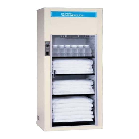
Description Description The Olympic Warmette is a large-capacity, free-standing warming cabinet. It is available in two sizes with the option of convenient see-through doors on the front and back for either size. The Warmette has a fully-enclosed, recirculating air system that warms blankets and bottles quickly and uniformly. - Page 14 Description Olympic Warmette Models 48/49 and 55/56 Instruction Manual...
-
Page 15: Section 2 Installation
S e c t i o n Installation This section describes how to install the Olympic Warmette Models 48/49 and 55/56. Read and be familiar with this manual before installing, operating, or servicing this device. To ensure operator, technician, and patient safety, use only as specified in CAUTION this manual. -
Page 16: Model 48/49 Anchor Holes
Assembling the Warmette After the Warmette is in place, adjust the leveling feet. Use the level to ensure the Warmette is evenly balanced. The Warmette must be bolted to the floor. CAUTION To install floor anchors: Access the anchor holes by removing the bottom tray (for Models 48/49, see Figure 2.1 and Figure 2.2;... -
Page 17: Inspecting The Heater
Inspecting the Heater Figure 2.3 Model 55/56 anchor holes Leveling feet Anchor holes Figure 2.4 Model 55/56 anchor hole placement 9.92 in. 25.97 in. 1.45 in. Center line 17.5 in. 6 in. 6 in. Inspecting the Heater If a Warmette fails to heat, a heater might have loosened during shipping. The Warmette has three 500W heaters per Plenum Assembly. -
Page 18: Screw Locations Inside Warmette Door
Inspecting the Heater Figure 2.5 Screw locations inside Warmette door Door stop Screws (4) Pull out and remove the front panel (see Figure 2.6). Figure 2.6 Removing the front panel Access panel Unhook and remove the plenum hold-down spring and bridge (see Figure 2.7). Push together the hold-down bridge and the spring, and then separate them. -
Page 19: Testing The Warmette
Testing the Warmette Testing the Warmette Test the Warmette after installing it or performing any maintenance or service procedure to ensure that all systems are functioning properly. To prepare the Warmette for testing: Plug in the power cord, then press the power switch to the (|) position. - Page 20 Electrical Requirements Olympic Warmette Models 48/49 and 55/56 Instruction Manual...
-
Page 21: Section 3 Operation
S e c t i o n Operation This section describes how to operate the Olympic Warmette Models 48/49 and 55/56. The Warmette Models 48 and 55 have clear doors on the front (see Figure 1.1 on page 1-3). The Models 49 and 56 have an additional set of doors on the back side. The Models 48/49 NOTE and 55/56 are operated in the same manner. -
Page 22: Controls And Signals
Operating the Warmette Temperature accuracy is ±10°F of selected temperature depending on the location in the cabinet. NOTE Controls and Signals The following controls and indicators are used when operating the Warmette (see Figure 3.1). Mains power switch: Turns the power ( | ) and (O). -
Page 23: Section 4 Maintenance
S e c t i o n Maintenance This section describes when and how to maintain the Olympic Warmette Models 48/49 and 55/56, including cleaning procedures. Electrical shock hazard when the enclosure is open. Always unplug the power cord from the electrical outlet before cleaning or maintaining the Warmette. WARNING The Warmette Models 48 and 55 have clear doors on the front (see Figure 1.1 on page 1-3). -
Page 24: Quarterly Maintenance
Quarterly Maintenance Ensure that the bottom tray is correctly placed for operating the Warmette. Ensure that the lint filter is not blocked. CAUTION Cleaning the Warmette Regularly clean the Warmette to keep it in optimal functioning condition. Required Items: Mild soap and water solution Liquid disinfectant Towel Do not allow liquid to enter the upper enclosure as liquids may cause electrical damage. -
Page 25: Annual Maintenance
Annual Maintenance Unscrew the three screws holding the filter, then remove the filter from the cabinet (see Figure 4.2). Clean the filter by holding it under a water faucet, then allow the filter to thoroughly air dry. Ensure the filter is dry, then place and secure with screws. Plug in the power cord. -
Page 26: Cleaning The Blower Housing And Blower Wheel
Annual Maintenance Cleaning the Blower Housing and Blower Wheel Required Items: Vacuum cleaner To clean the blower housing and blower wheel: Access the blower housing (see Replacing the Blower on page 6-9 for disassembly instructions). Vacuum accumulated dust and debris. Reassemble the Warmette. -
Page 27: Blower Assembly
Annual Maintenance Rotate to high. Allow the warmer to heat for 20 minutes. SET TEMP Connect an amp probe to the number 1 (hot) wire near the fuse holder. The amperage reading should be approximately 14.0A for 120V~ or 8A for 220V~. Interior parts of the cabinet and heating components such as the plenum may become hot. - Page 28 Annual Maintenance Olympic Warmette Models 48/49 and 55/56 Instruction Manual...
-
Page 29: Section 5 Troubleshooting
S e c t i o n Troubleshooting Should you experience difficulty when operating your Olympic Warmette , consult ® the following table. For problems not listed in the table, contact Natus Medical (see Technical Support on page 5-2). Table 5.1 Troubleshooting chart Problem... -
Page 30: Technical Support
Technical Support Technical Support For technical support, contact the Natus Medical Service Department at: Toll-free: 1-866-940-7143 (US/Canada) Phone: +1-206-767-3500 (worldwide) Fax: +1-206-767-0573 Email: Seattle_technical_service@natus.com Olympic Warmette Models 48/49 and 55/56 Instruction Manual... -
Page 31: Section 6 Service
To ensure performance to factory specifications, Natus Medical recommends that all replacement parts be those either manufactured or sold by Natus Medical. After all repair actions and tests are complete, perform the pre-operative test procedure in this manual (see on page 2-5) to ensure proper operation and compliance with published specifications. -
Page 32: Repair Procedures
Repair Procedures Repair Procedures Electrical shock hazard when the enclosure is open. Unplug the power cord from the electrical outlet before servicing the Warmette. WARNING Temperature Measurement Each Olympic Warmette is factory tested to ensure that it meets heating and safety specifications. -
Page 33: Replacing The Fuse
Repair Procedures Replacing the Fuse If the heater lamp does not illuminate, the heater remains off, and the blower does not run while the power is on, you may need to replace the fuse. Required Items: 1/4-in. nut driver Replacement fuse (part no. 200021) To remove the fuse: Press the power switch to the (O) position, then unplug the power cord. -
Page 34: Replacing The Mains Power Switch
Repair Procedures Figure 6.1 Access panel assembly — exploded view Spacer Thermostat Mounting screws (x2) Thermostat label Knob Heater indicator Heater indicator lamp cover lamp socket Access panel Mains power switch To reinstall the access panel: Reinstall the access panel, then securely tighten the screws (see Figure 6.1). Reinstall the shelf supports over the access panel, then securely tighten the screws. -
Page 35: Access Panel Assembly - Side View
Repair Procedures Push the power switch forward through the front of the Warmette cabinet (see Figure 6.2). Figure 6.2 Access panel assembly — side view FRONT BACK Temperature control knob Thermostat Capillary tube Heater indicator lamp and cover Lamp housing Butt splice connectors Spade connectors Mains power switch... -
Page 36: Replacing The Heater Indicator Lamp
Repair Procedures Replacing the Heater Indicator Lamp If the heater indicator lamp is burned out, perform the following procedure to replace it. Required Items: Heater indicator lamp (part no. 200002) 1/4-in. nutdriver To remove the heater indicator lamp: Press the power switch to the (O) position, then unplug the power cord. - Page 37 Repair Procedures Remove the indicator lamp cap and the mains power switch (see Replacing the Mains Power Switch on page 6-4). Remove and discard the thermostat label. Remove the two mounting screws on the front of the thermostat (see Figure 6.1 on page 6-4).
-
Page 38: Replacing The Thermostat Label
Repair Procedures Turn the control knob fully clockwise and loosen the two set screws. Rotate the knob slightly counterclockwise by half the gap between full rotation and the 150°F mark and then retighten the set screws. Replace the mains power switch (see page 6-4). Replace the access panel, shelf supports, and tray. -
Page 39: Replacing The Blower
Repair Procedures Replacing the Blower If air does not circulate or if the Warmette temperature is inconsistent throughout the device, the blower may need to be replaced. Required Items: 1/4-in. nutdriver 7/16-in. nutdriver To replace the blower: Press the power switch to the (O) position, then unplug the power cord. -
Page 40: Blower/Filter Assembly
Repair Procedures To remove the wire ties and old blower: Figure 6.5 Blower/Filter assembly Plenum Plenum hold-down bridge FRONT Plenum hold-down spring Blower Terminal strip BACK Since it is easy to clean the Warmette while the blower is removed, perform the annual maintenance and inspection at this time. -
Page 41: Replacing The Thermal Cut-Out
Repair Procedures Replacing the Thermal Cut-out If the thermal cut-out does not function properly (see Testing the Thermal Cut-out Function on page 4-4), replace the component by performing this procedure. Required Items: Thermal cut-out (part no. 200051) 1/4-in. nutdriver To remove the thermal cut-out: Press the power switch to the (O) position, then unplug the power cord. -
Page 42: Replacing The Heater
Repair Procedures Replacing the Heater The Warmette has three heaters on each side. If the Warmette does not heat, determine if the heater has failed (e.g. check the current to the unit. If it is much less than 14A (120V~) or 8A (220V~) and all connections appear functional, a failed heater is suspect. -
Page 43: Section 7 Replacement Parts
S e c t i o n Replacement Parts Use only Natus Medical-approved parts with the Warmette. NOTE Ordering Information To order Warmette parts and accessories, contact: Natus Medical Incorporated Customer Service Department Toll-free: 1-800-303-0306 Phone: +1-650-802-0400 Fax: +1-650-802-6620 Email: customer_service@natus.com... - Page 44 Ordering Information Olympic Warmette Models 48/49 and 55/56 Instruction Manual...
-
Page 45: Section 8 Specifications
S e c t i o n Specifications Intended Use Electrical The Warmettes are intended for warming fluids, Power Requirements (per module) blankets or other linens in a hospital setting. Voltage: 120–220V~, single phase Consumption: Dimensions — Model 48/49 14.0A (120V~) Dimensions 8.0A (220V~) Height:... - Page 46 External Connections Hospital-grade power cord (120V units) Product Item Catalog No. Warmette Model 48 ....56948 Warmette Model 49 (with rear door) ..56949 Warmette Model 55 .
-
Page 47: Appendix A Drawings And Schematics
A p p e n d i x Drawings and Schematics Figure 8.1 Model 48/49/55/56, Olympic Warmette Wiring Diagram, Drawing No. 700192 Rev. C Olympic Warmette Models 48/49 and 55/56 Instruction Manual... -
Page 48: Model 48/49/55/56, Olympic Warmette Schematic, Drawing No. 700193
Figure 8.2 Model 48/49/55/56, Olympic Warmette Schematic, Drawing No. 700193 Olympic Warmette Models 48/49 and 55/56 Instruction Manual... -
Page 49: Model 48/49/55/56, Olympic Warmette Drawing No. 700194
Figure 8.3 Model 48/49/55/56, Olympic Warmette Drawing No. 700194 Olympic Warmette Models 48/49 and 55/56 Instruction Manual... -
Page 50: Model 48/49/55/56 Olympic Warmette Drawing No. 700195
Figure 8.4 Model 48/49/55/56 Olympic Warmette Drawing No. 700195 Olympic Warmette Models 48/49 and 55/56 Instruction Manual...
Need help?
Do you have a question about the Olympic Warmette 48 and is the answer not in the manual?
Questions and answers