Table of Contents
Advertisement
Quick Links
Advertisement
Table of Contents
Troubleshooting

Summary of Contents for Phoenix LT4
- Page 1 Operation, Maintenance, and Parts Manual PHOENI LT4 Combination Lane Machine January 2022 / 61-900040-000 for the 110V LT4 Lane Machine 61-860334-110 220V LT4 Lane Machine 61-860334-220 Caution: Read this instruction manual before using the lane machine...
-
Page 3: Table Of Contents
1.1 Overview of Safety Labels ................1-1 Important Safety Information ................ 1-3 Section 2 – Introduction 2.1 Introduction to the Phoenix LT4 Lane Machine ..........2-1 2.2 Unpacking the Phoenix LT4 Lane Machine ..........2-4 2.3 Specifications, Dimensions, and Capacities ..........2-5 2.4 Phoenix LT4 Components Overview ............ - Page 4 5.1.1 General Operation ................5-2 5.1.2 Cleaning Operation ................5-6 5.1.3 Conditioning Operation ................ 5-8 5.2 Recovering if the Phoenix LT4 Stops on the Lane ........5-10 Section 6 – Determining the Oiling Pattern 6.1 Default Programs ..................6-1 6.1.1 Program A .................... 6-2 6.1.2 Program B ....................
- Page 5 Table of Contents, cont. Section 7 – Parts FRAME and BODY ....................7-5 Base Plate and Side Plates ................7-6 Hood Assembly ....................7-8 VACUUM and CLEANING SYSTEMS ..............7-9 Vacuum System ....................7-10 Vacuum Head Assembly ................. 7-12 Vacuum Head Solenoid & Bracket Assembly ..........7-13 Vacuum Head Tensioner Assembly ..............
- Page 6 Table of Contents (cont’d) MISCELLANEOUS ....................7-41 110V Power Cord Assembly ................7-42 220V Power Cord Assembly ................7-42 Buffer Pressure Adjusting Tool ............... 7-43 Wiring Diagram, 110-Volt Lane Machine ............7-44 Wiring Diagram, 220-Volt Lane Machine ............7-45 PART NUMBER INDEX ..................7-47...
- Page 7 SAFETY INFORMATION OVERVIEW OF LABEL SYMBOLS This guide contains information needed to properly operate and maintain the Phoenix LT4 Lane Machine. If any terms, concepts, or operations contained in this guide are unclear to the user, consult an experienced professional or Brunswick Customer Response Center at 1-800-YES-BOWL (1-800-937-2695).
- Page 8 Phoenix LT4 Lane Machine Operation, Maintenance, and Parts Manual Earth (Ground) Part Number 294-115-256 Protected Earth (Ground, Main) Part Number A-1058 MULTIPLE ICON LABELS Danger, Read Tech Manual, Do Not Operate with Guards Removed Part Number 294-009-005 Do Not Overfill...
-
Page 9: Important Safety Information
Safety Information IMPORTANT SAFETY INFORMATION WARNING! The following basic safety-related items must be followed in order to ensure the safe operation of the lane machine. Failure to follow these precautions could result in serious personal injury, damage to the lane machine, or both. ... - Page 10 Phoenix LT4 Lane Machine Operation, Maintenance, and Parts Manual IMPORTANT SAFETY INFORMATION, cont. DO NOT use flammable or toxic materials in the lane machine. Use only cleaners and conditioners specifically formulated for use by the bowling industry. Avoid splashing liquid when filling the cleaner tank and oil tanks. Follow all instructions and precautions on the product label.
- Page 11 Safety Information IMPORTANT SAFETY INFORMATION, cont. When not in use, secure the machine to prevent it from falling over and from other unintentional movement. During operation, pay attention to other persons in the area, especially children. Rev. Date: 01/22 61-900040-000...
-
Page 13: Section 2 - Introduction
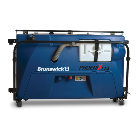
INTRODUCTION INTRODUCTION TO THE PHOENIX LT4 LANE MACHINE The Phoenix LT4 Lane Machine, shown in Figure 2- 1, is a versatile, total lane care machine that performs three operations: cleaning, conditioning, and standalone buffing. The cleaning operation removes dirt and oil from the lane. This can be performed alone or in combination with conditioning. - Page 14 Refer to Section 6 – Determining the Oil Pattern for more information. Factory Programming The Phoenix LT4 is capable of performing a single pass (the machine travels down the lane forward and returns in reverse) and double pass (the machine will travel down the lane a second time).
- Page 15 Additional information about the factory settings and adjusting them can be found in Section 3.10 – Cleaning and Conditioning. A printout of the specific cross-lane oil pattern produced by the Phoenix LT4 has been included in a yellow envelope. This printout contains important information about the machine’s initial settings and should be retained for the center's record.
-
Page 16: Unpacking The Phoenix Lt4 Lane Machine
Brunswick is not responsible for damage that occurs during shipment. Before first using the Phoenix LT4 Lane Machine, ensure all the components were shipped and that they arrived in good condition. It is also important to become familiar with how the machine operates. -
Page 17: Specifications, Dimensions, And Capacities
Introduction SPECIFICATIONS, DIMENSIONS, AND CAPACITIES Table 2- 1 below provides the electrical use, machine weight and dimensions, and tank capacities of the Phoenix LT4 Lane Machine. Table 2- 1 Electrical Single phase, 50/60 Hertz 1860 watts 110 V (US) 15.5 AMP 200 –... - Page 18 Phoenix LT4 Lane Machine Operation, Maintenance, and Parts Manual Table 2- 2 below lists the contents of the Phoenix LT4 Lane Machine package. Table 2- 2 Item Part Number Phoenix LT4 Lane Machine 61-860334-110 (110V) 61-860334-220 (220V) Power Cord 294-002-359 (110V)
-
Page 19: Phoenix Lt4 Components Overview
The following pages contain an overview of the Phoenix LT4 components. The hood has been hidden in these views which are meant to help familiarize the user with the Phoenix LT4. For detailed information about the components and their functions, refer to the Operation, Maintenance, and Parts sections of this manual. - Page 20 Phoenix LT4 Lane Machine Operation, Maintenance, and Parts Manual DESCRIPTION DESCRIPTION Oil Compartment E-Stop Switch Lift Handle Buffer Motor Vacuum Motor Oil Tank Waste Tank Transfer Rollers In-Line Filter Control Box Control Box Guard Touch Screen Vacuum Hose E-Stop Switch...
- Page 21 Introduction DESCRIPTION Power Cord Strap Start Switch Operating Casters Vacuum Motor Exhaust Port Waste Tank Guard Cleaner Flow Control Valve Cleaner Spray Nozzles Rev. Date: 01/22 61-900040-000...
- Page 22 Phoenix LT4 Lane Machine Operation, Maintenance, and Parts Manual DESCRIPTION DESCRIPTION Guide Roller Drive Wheel Front Roller Storage Caster Serial / Information Plate Oil Compartment Latch Drip Pad Buffer Brush End of Lane Sensor Handle Vacuum Head Idler Wheel Rev. Date: 01/22...
-
Page 23: Section 3 - Operation
Section 3 OPERATION The Phoenix LT4 Lane Machine is straightforward and easy to operate. The basic steps are: Place it on the lane Fill the cleaner and oil tanks Plug in the machine Select the operation ... - Page 24 Buffer brush & solenoids Oil transfer roller motor The Phoenix LT4 Lane Machine uses wicking foams to transport the oil from the oil tank to the transfer roller. The density and contact pressure of the wicking foams control the rate at which oil is moved to the transfer roller.
-
Page 25: The Phoenix Lt4 Lane Machine Controls
Section 6 - Determining the Oiling Pattern. THE PHOENIX LT4 LANE MACHINE CONTROLS The Phoenix LT4 Lane Machine features a touch screen, making it very simple to operate. The control panel, shown in Figure 3- 2, features four main components: the power inlet, power switch, E-STOP Button, and the touch screen. -
Page 26: The Touch Screen
Figure 3- 4 Program Buttons The Phoenix LT4 has the capability of storing four programs in its memory. These four programs (A, B, C, and D) are listed on the left side of the screen. The names of these programs cannot be changed. -
Page 27: Editing Program Specifications
Editing Program Specifications Editing the Pattern Specifications The Phoenix LT4 comes with four preprogrammed patterns that will produce a good bowling condition in most bowling centers. The distances of these patterns can be changed to best suit each bowling center. Table 3- 2 shows a close-up of the first and second pass edit buttons which are found on the right side of the screen. - Page 28 Phoenix LT4 Lane Machine Operation, Maintenance, and Parts Manual First Pass To edit the first pass, select the program to be changed on the Home screen. In the instance of Figure 3- 7, Program B has been selected as indicated by the ">"...
- Page 29 Operation Second Pass To edit the second pass, select the program to be changed on the Home screen. In the instance of Figure 3- 9, Program B has been selected as indicated by the ">" next to the letter "B." Figure 3- 9 Select the Edit Second Pass button.
- Page 30 Phoenix LT4 Lane Machine Operation, Maintenance, and Parts Manual Example From the factory, Program A is a single pass pattern with cleaning, oiling to 14 feet, and buffing to 40 feet. Suppose it is necessary to increase the first pass oil length to 15 feet, decrease buffing distance to 35 feet and add a second pass of oil to 7 feet, buff to 20 feet.
-
Page 31: The Run Screen
Factory Defaults Selecting Factory Defaults will reset all programs and settings to the factory default values. The factory default values for the Phoenix LT4 are listed in the Table 3- 3 below. Table 3- 3 Program Pass... -
Page 32: The Test Area
Phoenix LT4 Lane Machine Operation, Maintenance, and Parts Manual A warning message, shown in Figure 3- 17, will appear to confirm that the defaults should be restored. To proceed, select Reset All. Once Reset All is selected all customizations will be lost and cannot be recovered. - Page 33 Operation Vacuum Motor - Pressing the Vacuum Motor button turns on vacuum motor. This can be used to test the operation of the vacuum motor. Buffer Solenoid - Touching the Buffer Solenoid button engages both buffer solenoids. An audible click from the buffer solenoid relay inside the control box may also be heard.
-
Page 34: Error Messages
3.2.6 Error Messages The Phoenix LT4 Lane Machine has several monitoring features. When unexpected conditions occur, an error message will be displayed on the screen. This section is an overview of the error messages. - Page 35 Operation If Auto Back is selected, the machine will use the last lane distance reading before the error and return itself to the foul line. A screen similar to the one shown in Figure 3- 25 will be displayed when Auto Back is selected. Error Code 2 - End of Lane The End of Lane error, shown in Figure 3- 26, can occur under two circumstances.
-
Page 36: Putting The Phoenix Lt4 Into Position
Figure 3- 30 To put the Phoenix LT4 into the operating position from the storage position, stand facing the bottom of the machine and grab the lifting handle with both hands. Slowly lower the machine onto its operating caster wheels, which are shown in Figure 3- 31 on the following page. - Page 37 Figure 3- 31 To put the Phoenix LT4 into the storage position from the operating position, first switch off, unplug, remove the power cord, and then fold the handle across the machine. Stand in front of the machine (the side with the spray nozzles) and grab the lifting bar with both hands.
-
Page 38: The Handle
The handle, shown in Figure 3- 32 and Figure 3- , can be placed in any position from flat against the Phoenix LT4 housing to fully rearward and parallel with the floor. This allows the handle to be put in whatever position is comfortable for the user when operating, moving, or storing the Phoenix LT4. -
Page 39: Optical Sensor
3. Secure it with the hook-and-loop strap. Figure 3- 36 OPTICAL SENSOR The Phoenix LT4 Lane Machine is equipped with an Front Optical Sensor and Cover optical sensor that detects the end of the lane (EOL). Spray Head... - Page 40 Phoenix LT4 Lane Machine Operation, Maintenance, and Parts Manual NOTES To ensure the power cord does not affect the sensors, it is recommended that the cord be routed as described in Section 3.4 – The Handle. If the optical sensor causes the machine to lose power, it will not resume its operation on power up, but will return to the home screen.
-
Page 41: Cleaning Operation Components
Operation CLEANING OPERATION COMPONENTS The components used in the cleaning operation are shown in Figure 3- 38, Figure 3- and Figure 3- described below in Table 3- 4, Table 3- , and Table 3- , respectively. Figure 3- 38 Table 3- 4 Component Description Cleaner Tank... - Page 42 Phoenix LT4 Lane Machine Operation, Maintenance, and Parts Manual Figure 3- 39 Table 3- 5 Component Description Vacuum Motor The combined motor and pump provide the suction power for removing the cleaner and conditioner solution from the lane. The unit contains a replaceable seal (P/N A-8307) that provides an air tight connection between the vacuum pump and waste tank.
- Page 43 Operation Figure 3- 40 Table 3- 6 Component Description Rear Squeegee The squeegee glides along the lane surface, wiping up the emulsified oil/cleaner solution which is then drawn up into the vacuum head by suction. Agitator Foam This foam strip mixes the cleaner into the oil on the lane to improve cleaning efficiency.
-
Page 44: Lane Conditioning Components
Phoenix LT4 Lane Machine Operation, Maintenance, and Parts Manual LANE CONDITIONING COMPONENTS The lane conditioning components are shown in Figure 3- 41, 3- 42, and Figure 3- , and described below in Table 3- 7 and Table 3- , respectively. - Page 45 Operation IMPORTANT Always fill the oil tank slowly to allow the oil level in the indicator, as shown in Figure 3- 42, to adjust to the level in the tank. Never fill the oil tank above the mark on the oil tank level indicator or oil will overflow into the machine and onto the lane.
-
Page 46: Preparing For Use
3.8.1.1 Adding Cleaner The cleaner used must be compatible with the Phoenix LT4 Lane Machine and the center's lanes. Listed below are things that need to be kept in mind when choosing a cleaner and filling the cleaner tank. -
Page 47: Adding Oil
Operation Follow the steps below to fill the cleaner tank. 1. Remove the cap from the cleaner tank. 2. Insert the large red funnel into the tank opening. Leave a small gap to allow air to exit from the tank as it is filled. Note: The large red funnel must have a screen in place. -
Page 48: Defoaming The Waste Tank And Checking Hose Connections
If there are any leaks in the system, the Phoenix LT4 will not be able to adequately pick up the cleaner/oil emulsion from the lane. Perform the steps below to check the connections and tank placement. -
Page 49: Cleaning The Lane Head Area
CLEANING THE LANE HEAD AREA To clean the lane using the Phoenix LT4, place only the front two casters in the gutters and follow the procedure below. Placing only the front two casters in the gutters will allow the machine to clean the first 30 inches (76 cm) of the lane. - Page 50 The Home Screen The Home screen, shown in Figure 3- 45, is where all the functions of the Phoenix LT4 can be accessed. To clean and/or condition a lane, select the appropriate program by touching one of the program letters on the left side of the screen.
-
Page 51: Cleaning And Conditioning The Lanes
Push the handle down (toward the approach) then release it to allow the machine to travel down the lane. As the Phoenix LT4 makes its forward and reverse pass on the lane to complete the selected program, it performs the actions shown in Table 3- 10 on the following page. The table separates each action by operation, but the Phoenix LT4 performs the actions simultaneously when multiple operations are selected. - Page 52 Phoenix LT4 Lane Machine Operation, Maintenance, and Parts Manual Table 3- 10 CLEANER OPERATION OIL OPERATION BUFF OPERATION Sprays cleaner. Turns on the oil transfer Turns on the buffer roller motor. motor and lowers the Turns on the vacuum brush.
- Page 53 5 minutes. Cycle the power switch to reset. Once the Phoenix LT4 has returned to the approach and turned off the motors for the operations selected, it can be moved to the next lane or press the POWER switch to turn off the machine.
-
Page 54: Illustration
3.10.2 Illustration The following drawing illustrates where the Phoenix LT4 performs actions when cleaning, oiling for 20 feet, and buffing for 40 feet are enabled on the first pass; and then oiling to 15 feet, and buffing to 25 feet on the second pass. The center's actual settings might be different. -
Page 55: Section 4 - Maintenance And Adjustments
MAINTENANCE AND ADJUSTMENTS By performing the simple, periodic maintenance procedures given in this section, the Phoenix LT4 Lane Machine will be kept in good working order to produce high quality lane conditioning. In addition to the periodic maintenance procedures, this section also contains information about how to adjust and test the machine’s performance and how to replace the parts that... - Page 56 Phoenix LT4 Lane Machine Operation, Maintenance, and Parts Manual Perform the following tasks with the machine in the operating position: Oiling Area Check the oil level and add oil if needed. Ensure the cap is in place and securely tightened.
-
Page 57: Performing Weekly Maintenance
Maintenance and Adjustments Perform the following tasks with the machine in the storage position: Cleaning Area With a clean cloth, wipe the agitator foam and squeegee. Check the agitator foam and squeegee for nicks, tears, and gaps in their edges. ... -
Page 58: Testing The Phoenix Lt4 Lane Machine's Performance
The Phoenix LT4 Lane Machine has been designed and manufactured to perform years of worry-free lane conditioning. However, the cleaning and conditioning operations should be checked to ensure the components are set correctly and that the Phoenix LT4 is performing as expected. - Page 59 Pressure Adjustment Tool, RP-43 Tools Needed: Position the Phoenix LT4 about 2 feet down the lane from the foul line. Plug the Phoenix LT4 into a power source. Turn ON the machine’s POWER switch.
-
Page 60: Cleaning The Cleaner Tank Area
4.2.3 Cleaning the In-Line Filter To keep particles out of the cleaner solution delivery system, the Phoenix LT4 has an in- line filter. To check and clean the in-line filter, complete the steps below. Perform these steps with the machine in the operating position. -
Page 61: Checking The Waste Tank Seal
The vacuum pump to waste tank seal plays a critical role in the cleaning function of the Phoenix LT4 and should be inspected weekly. Any nicks or cuts, bent or rolled edges, excessively frayed or abraded areas, or lack of adhesion to the vacuum pump will impede the cleaning function. -
Page 62: Cleaning The Oil Tank Area
Phoenix LT4 Lane Machine Operation, Maintenance, and Parts Manual 4.2.6 Cleaning the Oil Tank Area Oil will accumulate on the sides and front of the oil tank, in the wicking foam areas, and on the frame below the tank. To clean these areas, complete the steps below. Perform these steps with the machine in the storage position away from the lane or the approach. -
Page 63: Cleaning The Buffer Brush
Maintenance and Adjustments 4.2.7 Cleaning the Buffer Brush When the buffer brush bristles get tangled, they can pick up lint or other things too large to be removed from the lane by the vacuum head. Oil will not be applied correctly if the buffer brush has tangles and debris in its bristles. -
Page 64: Performing Occasional Maintenance
Phoenix LT4 Lane Machine Operation, Maintenance, and Parts Manual PERFORMING OCCASIONAL MAINTENANCE At some point it will be necessary to adjust or replace parts as they wear out from normal use. This section contains information about some of the repairs that might need to be performed to the Phoenix LT4. - Page 65 Maintenance and Adjustments While it is not necessary to remove the hood in order to perform this procedure, removing the hood will improve access to the buffer linkages but will require that the hood be reinstalled to check the adjustment. To remove the hood, unlatch the oil compartment door latches, disconnect the vacuum hose and remove the waste tank, remove the cap from the...
- Page 66 Phoenix LT4 Lane Machine Operation, Maintenance, and Parts Manual Figure 4- 8 Increase Decrease Figure 4- 9 Reinstall the clevis pins and bowtie cotters. If the hood was removed, it must be reinstalled prior to testing the buffer pressure. If the hood was not removed, close and latch the oil compartment door.
-
Page 67: Rotating The Wicking Foams
Maintenance and Adjustments 4.3.2 Rotating the Wicking Foams Rotating the wicking foams allows for the reuse of the foams while providing a new wicking surface. The wicking foams should be rotated weekly or when waves or streaks appear in the oil pattern. Perform the following procedure to rotate the wicking foams with the machine in the storage or operating position in the maintenance area. -
Page 68: Lubricating The Chains
Phoenix LT4 Lane Machine Operation, Maintenance, and Parts Manual Install the wicking foam that was removed in Step 5 in the other end of the oil tank. Install it with its unused side facing out. Figure 4- 12 Repeat the operation for the remaining wicking foams. They can be reinstalled in their original locations. - Page 69 Maintenance and Adjustments Always ensure the Phoenix LT4 Lane Machine is disconnected from any power source before starting any maintenance, replacement, or repair task. Tools Needed: Oil can with nozzle dispenser or small, long- handled, stiff-bristled brush 5/32-inch hex wrench...
-
Page 70: Adjusting The Cleaner Spray
Phoenix LT4 Lane Machine Operation, Maintenance, and Parts Manual 4.3.4 Adjusting the Cleaner Spray The cleaner spray is critical to the cleaning function of the machine. Two types of adjustments can be made to the sprayer system: flow rate and direction. -
Page 71: Adjusting Cleaner Nozzle Direction
Maintenance and Adjustments Perform the following steps with the machine in the operating position to adjust cleaner flow. 1/16” hex wrench Tools Needed: Set Screw The flow valve may be locked into place by a set screw on the knurled knob. If it is, unlock the valve using a 1/16-inch hex wrench as shown in Figure 4- OPEN the valve by turning it counter clockwise to DECREASE cleaner spray. - Page 72 Phoenix LT4 Lane Machine Operation, Maintenance, and Parts Manual Always ensure the Phoenix LT4 Lane Machine is disconnected from any power source before starting any maintenance, replacement, or repair task. Tools Needed: 11/32" wrench #2 Phillips Screwdriver To adjust the angle of the middle spray head: 1.
-
Page 73: Clearing A Clogged Nozzle
Perform the procedure below with the machine in the operating position to clear a clogged nozzle. Always ensure the Phoenix LT4 Lane Machine is disconnected from any power source before starting any maintenance, replacement, or repair task. -
Page 74: Adjusting The Vacuum Head Height
Phoenix LT4 Lane Machine Operation, Maintenance, and Parts Manual Tools Needed: 7/8" wrench 1. Unlatch the oil compartment door latches, disconnect the vacuum hose and remove the waste tank, remove the cap from the cleaner tank, remove the two screws from each side of the hood as shown in Figure 4- 211, and lift the hood from the frame. - Page 75 The majority of centers will not to have to change the factory settings. If adjustments are necessary, they should not vary dramatically from the factory settings. Always ensure the Phoenix LT4 Lane Machine is disconnected from any power source before starting any maintenance, adjustment, replacement, or repair task.
-
Page 76: Adjusting The Vacuum Motor Position
The waste tank must be properly seated against the vacuum pump to ensure the proper vacuum seal. If there are any leaks in the system, the Phoenix LT4 will not be able to adequately pick up the cleaner / oil emulsion from the lane. -
Page 77: Adjusting The Optical Sensor
Unlike all other adjustments, it is necessary to have the Phoenix LT4 powered while adjusting the optical sensor. The two adjustments to the optical sensor are D-L and the sensitivity as shown in Figure 4- 29. The D-L refers to dark detection (normally closed) or light detection (normally open). -
Page 78: Adjusting The Handle Hinges
4.3.8 Adjusting the Handle Hinges The Phoenix LT4 handle can be placed in any position from flat against the Phoenix LT4 housing to parallel with the floor. This allows for the handle to be put in whatever position is most comfortable for the user who is operating, moving, or storing the Phoenix LT4. -
Page 79: Adjusting The Oil Tank Bars
Always ensure the Phoenix LT4 Lane Machine is disconnected from any power source before starting any maintenance, replacement, or repair task. -
Page 80: Adjusting Guide Roller Position
The Phoenix LT4 comes with its guide rollers positioned for maximum stability while operating on the lane. In very rare cases, this configuration may not work. The Phoenix LT4 is designed for the rear casters to hit the gutter ramps upon the machine’s return to the approach and prevent any contact or damage to the guide rollers. - Page 81 The following procedure should be done with the Phoenix LT4 in the storage position. Always ensure the Phoenix LT4 Lane Machine is disconnected from any power source before starting any maintenance, replacement, or repair task.
-
Page 82: Replacing Parts
Phoenix LT4 Lane Machine Operation, Maintenance, and Parts Manual 4. The belt should just barely give (1/8” or less of movement) under the pressure of being pushed down by one finger (approximately 2-3 lbs. of force). 5. Ensure that the buffer motor is parallel with the buffer brush. - Page 83 Maintenance and Adjustments vacuum head. Take care not to drop the nuts into the machine. Reinstall the nuts in the following pattern: one end, opposite end, middle, and then all remaining nuts. 3. Before tightening the nuts, ensure the agitator foam and backer are flat against the vacuum head channel.
-
Page 84: Replacing The Buffer Brush
Phoenix LT4 Lane Machine Operation, Maintenance, and Parts Manual 4.4.2 Replacing the Buffer Brush As the buffer brush wears, gets dirty, bristles tangle and break off, it will no longer apply the oil properly. The buffer brush should be replaced every 1,080,000 feet of travel or when adjusting the brush pressure doesn’t significantly improve its performance. -
Page 85: Replacing The Wicking Foams
The wicking foams should be replaced every 180,000 to 270,000 feet of travel. However, if the Phoenix LT4 starts leaving a wavy or streaky oil pattern or the oil output has decreased and rotating the wicking foams does not alleviate the problem, they should be replaced immediately. - Page 86 Phoenix LT4 Lane Machine Operation, Maintenance, and Parts Manual When cutting new wicking foams from a section of factory bulk length, cut and discard approximately 1/2" from the factory cut edge. Failure to do so could result in inconsistent oil flow through the wicking foam at the end.
- Page 87 Figure 4- 41 NOTES The Phoenix LT4 cannot be used for approximately 1-2 hours after the wicking foams have been replaced. This waiting period is required to allow the oil to be wicked to the top of the foam. To verify the oil has wicked to the top of the foam, check the color of the wicking foam.
-
Page 88: Replacing The Waste Tank Seal
Phoenix LT4 Lane Machine Operation, Maintenance, and Parts Manual Unfasten the clasps over the oiling components at the back of the Phoenix LT4 and open the compartment door. Remove the oil tank spring and the two retaining pins on either side of the oil tank as shown in Figure 4- 42. -
Page 89: Replacing Fuses
4.4.5 Replacing Fuses The Phoenix LT4 contains six fuses that are used to protect its electrical components. All six fuses are located on top of the control box as shown in Figure 4- 444. Several spare fuses have been included in the yellow envelope that was shipped with the machine. - Page 90 Phoenix LT4 Lane Machine Operation, Maintenance, and Parts Manual Table 4- 2 Voltage 110 V 220V Label Current, A Part Number Current, A Part Number Cleaner Pump 748-610-600 748-901-111 Buffer Motor 748-510-400 748-511-405 Vacuum Motor 748-510-400 748-511-405 Drive Motor 6.25...
-
Page 91: Replacing The Optical Sensor
4.4.6 Replacing the Optical Sensor The optical sensor stops the Phoenix LT4 at the end of the lane. A faulty optical sensor could cause the machine to stop too soon or not at all. The instructions below tell how to adjust and replace the front sensor. - Page 92 Phoenix LT4 Lane Machine Operation, Maintenance, and Parts Manual Connector Wire Tie & Mounting Block Figure 4- 38 3. Disconnect the optical sensor cable. 4. Being careful not to cut into any wires, remove the wire tie securing the optical sensor cable to the cable tie anchor.
-
Page 93: Updating The Phoenix Lt4 Software
Maintenance and Adjustments UPDATING THE PHOENIX LT4 SOFTWARE From time to time the Phoenix LT4 firmware may be updated to include new features or correct bugs in the software. In the event that a newer version is available, the software can be upgraded easily. - Page 94 Phoenix LT4 Lane Machine Operation, Maintenance, and Parts Manual 6. Insert the USB flash drive into the USB on the control box then close and latch the oil compartment door. 7. Take note of the time, plug the machine in, and turn the power switch on.
-
Page 95: Section 5 - Troubleshooting
The solutions given in this section should be performed only by experienced operators who are accustomed to working with machines, electrical components, and parts drawings. Do not attempt to repair or adjust the Phoenix LT4 Lane Machine if any of the steps given for a possible solution are not understood. -
Page 96: General Operation
Troubleshooting 5.1.1 General Operation PROBLEM SOLUTION The machine doesn’t turn Ensure that there is power to the outlet (the breaker isn’t on/the touch screen doesn’t open or tripped) and that it is of the correct voltage for the light up. machine. - Page 97 Phoenix LT4 Lane Machine Operation, Maintenance, and Parts Manual 5.1.1 General Operation, continued PROBLEM SOLUTION The drive motor continues Ensure all four caster wheels are in the gutter before the second press of the start button. Refer to Section 3.9 –...
- Page 98 Troubleshooting 5.1.1 General Operation, continued PROBLEM SOLUTION The machine does not fit The guide rollers are set at the factory to fit synthetic lanes. tightly against the sides of For wood lanes, the guide roller may need to be adjusted. the lane or runs Depending on the centers lanes, the guide rollers may need crooked/skews down the...
- Page 99 Phoenix LT4 Lane Machine Operation, Maintenance, and Parts Manual 5.1.1 General Operation, continued PROBLEM SOLUTION The machine hums or buzzes. Use extreme care when servicing solenoids. The surfaces can be very hot and a severe pinching hazard exists under the hood.
-
Page 100: Cleaning Operation
Troubleshooting 5.1.2 Cleaning Operation PROBLEM SOLUTION The nozzle(s) is not Make sure the cleaning operation is selected. spraying cleaner. Ensure there is cleaner in the cleaner tank. Ensure the cleaner pump is running by pressing the cleaner pump button in the test area. If not, check the cleaner pump fuse. - Page 101 Phoenix LT4 Lane Machine Operation, Maintenance, and Parts Manual 5.1.2 Cleaning Operation, continued PROBLEM SOLUTION Residue is left on the lane Check that the waste tank is seated correctly against the after the Phoenix LT4 waste tank seal and that the seal is not rolled or damaged.
-
Page 102: Conditioning Operation
Troubleshooting 5.1.3 Conditioning Operation PROBLEM SOLUTION Parts of the oil pattern look Check the condition of the wicking foams and rotate or like a “washboard” or replace as needed. Refer to Section 4.3.2 – Rotating the Wicking Foams and/or Section 4.4.3 – Replacing the chattered. - Page 103 Phoenix LT4 Lane Machine Operation, Maintenance, and Parts Manual 5.1.3 Conditioning Operation, continued PROBLEM SOLUTION The machine hums or The buffer brush pressure is too high. Reposition the buffer chatters when it is buffing. brush to reduce the pressure. Check for sufficient buffer belt tension.
-
Page 104: Recovering If The Phoenix Lt4 Stops On The Lane
Figure 5- 3 slowly to avoid damage to the vacuum head. Once the Phoenix LT4 has returned to the foul line and the problem has been corrected, restart the machine to have it perform the same operation(s) it was performing when it stopped. -
Page 105: Section 6 - Determining The Oiling Pattern
DEFAULT PROGRAMS In the following pages, each of the Phoenix LT4's factory programs is explained in detail. Included, is a graphic depiction of the processes the machine will perform on the lane and a typical graph of the oil pattern. A legend for the illustration of the programs is shown in Table 6- 1. -
Page 106: Program A
Phoenix LT4 Lane Machine Operations, Maintenance, and Parts Manual 6.1.1 Program A Program A is a single pass oil pattern that gives novice bowlers a predictable bowling condition. It can be used for recreational or open play. The default specifications for Program A are shown below in Figure 6- 1. -
Page 107: Program B
Determining The Oil Pattern 6.1.2 Program B Program B is a double pass oil pattern designed for amateur leagues or clubs whose bowlers may have performance bowling balls. It will protect the lanes from damage due to performance bowling balls while providing a more competitive condition. The specifications for Program B are shown below in Figure 6- 3. -
Page 108: Program C
Phoenix LT4 Lane Machine Operations, Maintenance, and Parts Manual 6.1.3 Program C Program C is a double pass oil pattern designed for tournaments and leagues whose bowlers will use high performance bowling balls. Program C will protect the lanes from damage due to performance bowling balls while providing a highly competitive condition. -
Page 109: Program D
Determining The Oil Pattern 6.1.4 Program D Program D is a cleaning only pass as shown in Figure 6- 7. It will not add any oil to the lane and can be used to test the cleaning function of the machine or prepare the lane for inspection. -
Page 110: How The Phoenix Lt4 Applies Oil
HOW THE PHOENIX LT4 APPLIES OIL The Phoenix LT4 uses wicking foams to transport the oil from the oil tank onto the oil transfer roller. The oil is moved through the wicking foams by capillary action. The density of the foams determines how much oil is moved in a given amount of time and space. - Page 111 Adding or removing a second oiling or buffing pass Using higher or lower flow wicking foams The second pass option runs the Phoenix LT4 down the lane a second time. During this transit, more oiling and buffing will occur. The second pass settings are independent of the first pass settings.
-
Page 112: Finger Smear Technique
Different types of oil patterns can be created with the Phoenix LT4 by changing the wicking foams and the adjustment bars on the top of the oil tank. The Phoenix LT4 is shipped with two #10 (medium-low) output foams for the outside 8 inches on both sides of the lane, two #6 (medium-high) foams along the next three inches (the track) on each side of the lane, and two #4 (super-high) output foams (10 inches each) for the middle 20 inches of the lane. -
Page 113: Wicking Foam Densities
A set of replacement wicking foams of different densities was supplied with the Phoenix LT4 Lane Machine. Each density of wicking foam is printed with a number for easy identification. The higher the number printed on the foam, the higher the foam’s density, and therefore the lower the oil output. -
Page 114: Head To Backend Transition Zone
If the lane is not buffed past the oiling distance, a sharp break between the oiled and dry surfaces is created. If the Phoenix LT4 continues to buff, the remaining oil in the brush will be applied to the lane until the buffer brush runs dry or reaches the end of the buffing area. The amount of oil will gradually decrease in both length and slightly in width as the machine buffs down the lane. -
Page 115: Troubleshooting
(if the center is certified) requirements in the area of the lane to which oil is applied. The amount of oil the Phoenix LT4 applies to the buffed area of the lane is determined by the amount of oil applied to the oiled area, the oiling distance, and the buffing distance. - Page 116 Phoenix LT4 Lane Machine Operations, Maintenance, and Parts Manual 800-937-2695). Additionally, Technical Support can be reached by e-mail at techsupport@brunbowl.com or via fax at 1-231-725-4667. Table 6- 3 Dry spots in the oiled If there are some dry spots but the rest of the lane has the...
- Page 117 Determining The Oil Pattern their oil output eliminates the problem. If the problem persists, the buffer brush may need to be replaced. If the brush has been contaminated with grease, remove and clean. If issue persists, replace the buffer brush. For more information about the buffer brush, refer to Section 4 - Maintenance and Adjustments.
- Page 118 Phoenix LT4 Lane Machine Operations, Maintenance, and Parts Manual Rev. Date: 01/22 6-14 61-900040-000...
-
Page 120: Section 7 - Parts
Phoenix LT4 Lane Machine Operation, Maintenance, and Parts Manual Section 7 PARTS Rev. Date 01/22 61-900040-000... - Page 121 Phoenix LT4 Lane Machine Operation, Maintenance, and Parts Manual This section contains parts drawings as well as wiring diagrams for the Phoenix LT4 Lane Machine. The drawings are shown within functional groupings, as listed on the next page. Use the drawings in the section for reference when repairing or replacing parts on the machine. Order any replacement parts using the part numbers listed in the adjacent tables.
- Page 122 Phoenix LT4 Lane Machine Operation, Maintenance, and Parts Manual FRAME and BODY OILING and BUFFING 7-6 Base Plate and Side Plates 7-26 Oiling and Buffing System 7-8 Hood Assembly 7-28 Transfer Roller Assembly VACUUM and CLEANER SYSTEMS 7-29 Transfer Roller Support Assembly...
- Page 123 Phoenix LT4 Lane Machine Operation, Maintenance, and Parts Manual This Page Intentionally Left Blank. Rev. Date 01/22 61-900040-000...
-
Page 124: Frame And Body
Phoenix LT4 Lane Machine Operation, Maintenance, and Parts Manual FRAME and BODY Rev. Date 01/22 61-900040-000... - Page 125 Phoenix LT4 Lane Machine Operation, Maintenance, and Parts Manual Frame Assembly – Base Plate and Side Plates Rev. Date 01/22 61-900040-000...
- Page 126 Phoenix LT4 Lane Machine Operation, Maintenance, and Parts Manual Frame Assembly – Base Plate and Side Plates NUMBER DESCRIPTION NUMBER DESCRIPTION 294-116-001 BASE PLATE ASSEMBLY 294-116-011 STORAGE CASTER, 2-INCH 294-116-003 SIDE PLATE ASSEMBLY, RIGHT HAND 294-115-614 OPERATING CASTER, 2-INCH 294-116-005...
-
Page 127: Hood Assembly
Phoenix LT4 Lane Machine Operation, Maintenance, and Parts Manual Hood Assembly – 294-116-215 NUMBER DESCRIPTION 294-115-560 CLEVIS PIN 294-115-561 E-CLIP 294-115-566 DRAW LATCH ASM 294-116-214 HOOD ASM (INCLUDES 1, 2 & 4) 808-549-080 SCREW, BUTTON HEAD, 1/4-20 X 1/2 A-0113 EXTENSION SPRING Rev. -
Page 128: Vacuum And Cleaning Systems
Phoenix LT4 Lane Machine Operation, Maintenance, and Parts Manual VACUUM and CLEANER SYSTEMS Rev. Date 01/22 61-900040-000... -
Page 129: Vacuum System
Phoenix LT4 Lane Machine Operation, Maintenance, and Parts Manual Vacuum System Rev. Date 01/22 7-10 61-900040-000... - Page 130 Phoenix LT4 Lane Machine Operation, Maintenance, and Parts Manual Vacuum System NUMBER DESCRIPTION NUMBER DESCRIPTION 294-116-147 VAC HEAD ASM 04-120 HOSE CLAMP 294-115-113 VAC HOSE ASM 294-116-148 EXHAUST DIVERTER 294-115-233 WASTE TANK GUARD ASM 801-749-081 SCREW, FLANGE HEAD HEX, 1/4-20 X 1/2 294-116-031 VAC MOTOR &...
-
Page 131: Vacuum Head Assembly
Phoenix LT4 Lane Machine Operation, Maintenance, and Parts Manual Vacuum Head Assembly - 294-116-147 NUMBER DESCRIPTION NUMBER DESCRIPTION 01-051 NUT, NYLON LOCK, 1/4-20 294-116-142 AGITATOR FOAM 294-116-129 ARM, VAC HEAD 294-116-146 VAC HEAD BAR 294-116-132 PIVOT BLOCK, VAC HEAD 702-108-000... -
Page 132: Vacuum Head Solenoid & Bracket Assembly
Phoenix LT4 Lane Machine Operation, Maintenance, and Parts Manual Vacuum Head Solenoid & Bracket Assembly Vacuum Head Tensioner Assembly – 294-116-128 NUMBER DESCRIPTION NUMBER DESCRIPTION 01-080 PIN, COTTER, 1/16 X 1/2 LG 01-021 SCREW, PAN HEAD, 10-32 X 1/2 01-495... -
Page 133: Vacuum Hose Assembly
Phoenix LT4 Lane Machine Operation, Maintenance, and Parts Manual Vacuum Hose Assembly & Clamp NUMBER DESCRIPTION 04-120 HOSE CLAMP 04-150 SLIP ADAPATER Vacuum Motor & Bracket Assembly NUMBER DESCRIPTION NUMBER DESCRIPTION 02-214 VAC MOTOR, 110V 760-019-223 CRIMP TERMINAL, FEMALE, 14-20 AWG... -
Page 134: Waste Tank & Bracket Assembly
Phoenix LT4 Lane Machine Operation, Maintenance, and Parts Manual Waste Tank & Bracket Assembly NUMBER DESCRIPTION NUMBER DESCRIPTION 01-089 RIVET, 1/8 DIA X 3/8 LG, ALUMINUM 809-849-085 SCREW, HEX, 1/4-20 X 1/2 01-148 SCREW, FLAT HEAD MACHINE, 1/4-20 X 3/4... -
Page 135: Cleaner System
Phoenix LT4 Lane Machine Operation, Maintenance, and Parts Manual Cleaner System Rev. Date 01/22 7-16 61-900040-000... - Page 136 Phoenix LT4 Lane Machine Operation, Maintenance, and Parts Manual Cleaner System NUMBER DESCRIPTION NUMBER DESCRIPTION 294-116-049 CLEANER PUMP & FITTINGS, 110V 294-115-650 DRIP TRAY 294-116-048 CLEANER PUMP & FITTINGS, 220V 294-116-105 CLEANER TANK & BRACKET ASM 294-116-238 TYGOTHANE TUBE, 16 IN...
- Page 137 Phoenix LT4 Lane Machine Operation, Maintenance, and Parts Manual Cleaner Filter Assembly- 294-115-673 Flow Control Valve Assembly - 294-116-151 NUMBER DESCRIPTION NUMBER DESCRIPTION 04-322 FILTER BOWL 294-115-071 STEM ADAPTER, 1/4 MPT X 3/8 04-322-1 MESH SCREEN FILTER (NOT SHOWN) 294-115-074...
- Page 138 Phoenix LT4 Lane Machine Operation, Maintenance, and Parts Manual 294-116-105 - Cleaner Tank & Bracket Assembly NUMBER DESCRIPTION 01-089 RIVET, 1/8 DIA X 3/8 LG, ALUMINUM 02-539 CABLE MOUNTING BLOCK, 3/4 X 3/4 294-115-072 STEM ADAPTER, 3/8 MPT X 3/8...
- Page 139 Phoenix LT4 Lane Machine Operation, Maintenance, and Parts Manual This Page Intentionally Left Blank. Rev. Date 01/22 7-20 61-900040-000...
- Page 140 Phoenix LT4 Lane Machine Operation, Maintenance, and Parts Manual DRIVE SYSTEM Rev. Date 01/22 7-21 61-900040-000...
- Page 141 Phoenix LT4 Lane Machine Operation, Maintenance, and Parts Manual Drive Assembly NUMBER DESCRIPTION NUMBER DESCRIPTION 294-116-045 DRIVE MOTOR ASM, 110V 294-116-030 DRIVE SHAFT ASM 294-116-039 DRIVE MOTOR ASM, 220V 294-116-036 DRIVE CHAIN 801-749-081 SCREW, FLANGE HEAD HEX, 1/4-20 X 1/2...
- Page 142 Phoenix LT4 Lane Machine Operation, Maintenance, and Parts Manual Drive Shaft Assembly - 294-116-030 NUMBER DESCRIPTION 294-116-027 DRIVE SHAFT SLEEVE 294-116-028 LEFT HAND DRIVE SHAFT END 294-116-029 RIGHT HAND DRIVE SHAFT END 913-437-100 PIN, ROLL, 3/16 X 5/8 LG Left Hand Drive Shaft End -294-116-028...
-
Page 143: Drive Shaft Bearing Block Assembly
Phoenix LT4 Lane Machine Operation, Maintenance, and Parts Manual Drive Shaft Bearing Block Assembly - 294-116-034 NUMBER DESCRIPTION 294-012-131 RETAINING RING, BEARING BLOCK 294-116-033 BEARING BLOCK, DRIVE SHAFT 701-035-040 BEARING, 12 mm X 28 mm X 8 mm Drive Motor Assembly... -
Page 144: Oiling And Buffing System
Phoenix LT4 Lane Machine Operation, Maintenance, and Parts Manual OILING and BUFFING SYSTEM Rev. Date 01/22 7-25 61-900040-000... - Page 145 Phoenix LT4 Lane Machine Operation, Maintenance, and Parts Manual Oiling & Buffing System Rev. Date 01/22 7-26 61-900040-000...
- Page 146 Phoenix LT4 Lane Machine Operation, Maintenance, and Parts Manual Oiling & Buffing System NUMBER DESCRIPTION NUMBER DESCRIPTION 01-024 SCREW, PAN HEAD, 10-32 X 1 294-116-090 LEFT HAND BUFFER MOUNTING ASM 294-116-093 RIGHT HAND BUFFER MOUNTING ASM 294-116-025 BUFFER MOTOR NUT PLATE...
- Page 147 Phoenix LT4 Lane Machine Operation, Maintenance, and Parts Manual Transfer Roller Drive Assembly - 294-116-062 NUMBER DESCRIPTION NUMBER DESCRIPTION 01-009 SCREW, PAN HEAD, 8-32 X 3/8 294-116-059 TRANSFER ROLLER SUPPORT ASM 01-016 WASHER, EXT TOOTH LOCK, #8 294-116-060 SPROCKET, #25 CHAIN, 22T...
-
Page 148: Transfer Roller Support Assembly
Phoenix LT4 Lane Machine Operation, Maintenance, and Parts Manual Transfer Roller Support Assembly - 294-116-059 NUMBER DESCRIPTION 04-017 BUSHING, FLANGED, 3/8 X 1/2 X 3/8 294-116-058 TRANSFER ROLLER SUPPORT ARM Roller Shaft Support Assembly - 294-116-057 NUMBER DESCRIPTION 04-017 BUSHING, FLANGED, 3/8 X 1/2 X 3/8... -
Page 149: Left Hand Buffer Solenoid Assembly
Phoenix LT4 Lane Machine Operation, Maintenance, and Parts Manual Left Hand Buffer Solenoid Assembly NUMBER DESCRIPTION 01-080 PIN, COTTER, 1/16 X 1/2 LG 01-495 PIN, CLEVIS, 3/16 X 1-1/4 LG 294-002-032 SOLENOID, 110V, 60HZ, RIGHT HAND 294-002-275 SOLENOID, 220V, 50HZ, RIGHT HAND... - Page 150 Phoenix LT4 Lane Machine Operation, Maintenance, and Parts Manual Left Hand Buffer Mounting Assembly - 294-116-090 NUMBER DESCRIPTION 294-116-085 BUFFER PIVOT SHAFT 294-116-086 BUFFER PIVOT MOUNTING BLOCK 294-116-088 SWIVEL END BEARING 294-116-089 LEFT HAND BUFFER ARM 701-406-108 BUSHING, FLANGED, 1/2 X 5/8 X 3/4 X 1/8...
-
Page 151: Oil Tank Lift Assembly
Phoenix LT4 Lane Machine Operation, Maintenance, and Parts Manual Oil Tank Assembly Rev. Date 01/22 7-32 61-900040-000... - Page 152 Phoenix LT4 Lane Machine Operation, Maintenance, and Parts Manual Oil Tank Assembly NUMBER DESCRIPTION NUMBER DESCRIPTION 01-009 SCREW, PAN HEAD, 8-32 X 3/8 294-115-516 SCREW, THREAD FORMING, 10-24 X 3/4 01-109 WASHER, FLAT, #8 294-115-530 ADJUSTMENT BAR, 3-INCH 04-093 RUBBER DIPSTICK SEAL...
-
Page 153: Buffer Motor Assembly
Phoenix LT4 Lane Machine Operation, Maintenance, and Parts Manual Buffer Motor Assembly NUMBER DESCRIPTION 01-041 SCREW, SET, CUP POINT 1/4-20 X 1/4 294-002-268 BUFFER MOTOR 294-116-069 BUFFER MOTOR PULLEY 294-116-071 BUFFER MOTOR ASM, 110V (INC. 2,3,4, & 5) 294-116-070 BUFFER MOTOR ASM, 220V (INC. 2,3,4, & 5) 294-116-079 BUFFER MOTOR PIGTAIL (INC. -
Page 154: Control System
Phoenix LT4 Lane Machine Operation, Maintenance, and Parts Manual CONTROL SYSTEM Rev. Date 01/22 7-35 61-900040-000... -
Page 155: Control System Components
Phoenix LT4 Lane Machine Operation, Maintenance, and Parts Manual Control System Components NUMBER DESCRIPTION NUMBER DESCRIPTION 088-000-245 OPTICAL SENSOR ASM 711-501-001 GROMMET, 3/16 X 5/8 X 3/16, RUBBER 294-115-677 GROUND BAR ASM 721-510-029 VIBRATION MOUNT, 8-32 X 1/2, MALE-FEMALE 294-116-053... -
Page 156: Optical Sensor Assembly
Phoenix LT4 Lane Machine Operation, Maintenance, and Parts Manual Optical Sensor Assembly - 088-000-245 NUMBER DESCRIPTION 745-020-328 CONNECTOR, 4 POSITION 760-010-234 CRIMP TERMINAL, 18-24 AWG Counter Wheel Assembly NUMBER DESCRIPTION 294-115-046 ENCODER 294-116-145 ENCODER SHAFT 294-116-162 TOOTH COUNTER WHEEL 294-116-163... -
Page 157: Control Box Assembly
Phoenix LT4 Lane Machine Operation, Maintenance, and Parts Manual 110V Control Box Assembly - 294-116-195 220V Control Box Assembly - 294-116-194 Rev. Date 01/22 7-38 61-900040-000... - Page 158 Phoenix LT4 Lane Machine Operation, Maintenance, and Parts Manual NUMBER DESCRIPTION NUMBER DESCRIPTION 01-005 WASHER, EXT TOOTH LOCK, #6 294-116-144 CAPACITOR ASM 01-008 SCREW, PAN HEAD, 8-32 X 1/4 294-116-181 RELAY BOARD ASM 01-016 WASHER, EXT TOOTH LOCK, #8 294-116-183...
-
Page 159: Handle Assembly
Phoenix LT4 Lane Machine Operation, Maintenance, and Parts Manual Handle Assembly - 294-115-555 NUMBER DESCRIPTION NUMBER DESCRIPTION 01-058 SCREW, HEX HEAD THREAD FORMING, #8 X 3/8 294-115-082 HANDLE PIVOT BOSS 01-130 RIVET, 1/8 DIA X 1/2 LG, ALUMINUM 294-115-695 FLANGED TENSION BUSHING... - Page 160 Phoenix LT4 Lane Machine Operation, Maintenance, and Parts Manual MISCELLANEOUS Rev. Date 01/22 7-41 61-900040-000...
- Page 161 Phoenix LT4 Lane Machine Operation, Maintenance, and Parts Manual 294-002-359 110V Power Cord Assembly NUMBER DESCRIPTION 02-238 WIRE, 12/3, TYPE SJTO 02-397 125V, 20A, MALE PLUG 04-443 SUPPORT GRIP, SINGLE EYE, SINGLE WEAVE 294-002-219 CONNECTOR BODY Detail for wire connections...
- Page 162 Phoenix LT4 Lane Machine Operation, Maintenance, and Parts Manual RP-43 Buffer Pressure Adjusting Tool NUMBER DESCRIPTION 01-108 SCREW, PAN HEAD, 6-32 X 1/4 04-403 RECESSED BUMPER Rev. Date 01/22 7-43 61-900040-000...
- Page 163 Phoenix LT4 Lane Machine Operation, Maintenance, and Parts Manual Wiring Diagram 110V Lane Machine – P/N 400-294-020 Rev. Date 01/22 7-44 61-900040-000...
- Page 164 Phoenix LT4 Lane Machine Operation, Maintenance, and Parts Manual Wiring Diagram 220V Lane Machine – P/N 400-294-019 Rev. Date 01/22 7-45 61-900040-000...
- Page 165 Phoenix LT4 Lane Machine Operation, Maintenance, and Parts Manual This Page Intentionally Left Blank. Rev. Date 01/22 7-46 61-900040-000...
- Page 166 Phoenix LT4 Lane Machine Operation, Maintenance, and Parts Manual PART NUMBER INDEX Rev. Date 01/22 61-900040-000 7-47...
- Page 167 Phoenix LT4 Lane Machine Operation, Maintenance, and Parts Manual 01-005 ......7-39 294-002-033 .... 7-13, 7-30 294-115-677 ..... 7-36 01-008 ......7-39 294-002-150 ..... 7-39 294-115-678 ..... 7-39 01-009 ..... 7-28, 7-33 294-002-214 ..... 7-39 294-115-695 ..... 7-40 01-014 ......7-24 294-002-219 .....
- Page 168 Part Number Index 294-116-085 ..... 7-31 294-116-167 ..... 7-37 809-849-100 .... 7-11, 7-13 294-116-086 ..... 7-31 294-116-169 ..... 7-36 809-849-125 ..... 7-19 294-116-088 ..... 7-31 294-116-181 ..... 7-39 809-865-205 ..... 7-40 294-116-089 ..... 7-31 294-116-183 ..... 7-39 810-206-501 ..... 7-37 294-116-090 ....
Need help?
Do you have a question about the LT4 and is the answer not in the manual?
Questions and answers