Table of Contents
Advertisement
Advertisement
Table of Contents

Related Manuals for Euromatic STILO

Summary of Contents for Euromatic STILO
- Page 1 Installation manual STILO STILO/S STILO/S AUTOMATION FOR SWING GATES...
-
Page 3: Table Of Contents
Outward opening page 3.4.4 Pillar bracket T1 ....................page Gate bracket S3 (for Stilo only) ....................page Gate bracket S4 (for Stilo S only) ..................... page 4. MANUAL RELEASE ................................ page 5. MAINTENANCE ................................. page 6. PHASING OUT AND DISPOSAL .......................... -
Page 4: General Safety Precautions
Keep any remote control devices (i.e. transmitters) away from the children as well. INTENDED USE AND APPLICATION STILO operator is designed to automate swing gates. The use of this product for purposes other than those described above and installation executed in a manner other than as instructed in this technical manual are prohibited. -
Page 5: Technical Features
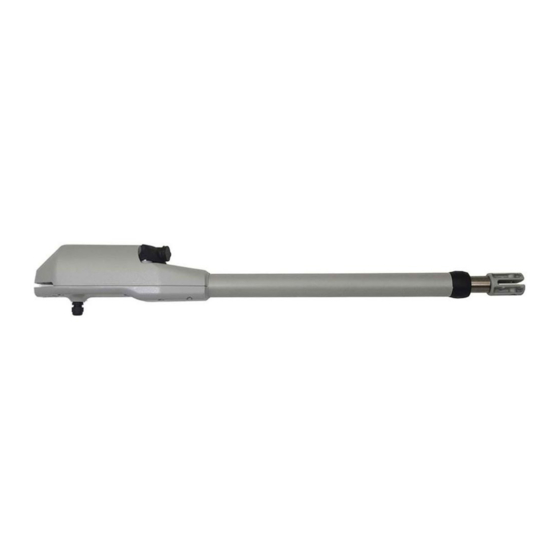
Open = 1140 mm Stilo 4: Closed = 915 mm Stilo 4: Open = 1240 mm Stilo S4: 1040 mm INSTALLATION Preliminary checks Before installing make sure: Weight, dimensions and gate construction are proper for the operator you intend to buy... -
Page 6: Tools And Materials (Not Included)
TOOLS AND MATERIALS (NOT INCLUDED) PILLARS AND WALLS stainless steel concrete brick inox/alu. tubular Ø 15mm Ø 18mm LEAF wood stainless steel/alu 2 +2... -
Page 7: Wiring
WIRING INSTALLATION OVERVIEW OUTER VIEW (pic. A) 230V 3 x 1,5 + T INNER VIEW Control panel 2 x 1,5 + T rx 4 x 0,50 mm² Photocells C¹ tx 2 x 0,50 mm² Photocells N.B.: The number of tubes and cables 2 x 0,50 mm²... -
Page 8: Installing The Operator
The ideal approach is to fix the brackets complying with the measures A and B as indicated in the below table for an opening angle of 90° (picture E). Stilo 3 = max 150 mm Stilo 4 = max 175 mm 90° Pic. E Stilo 3 A=150 B=150 Stilo 4 A=200 B=200 minimo 150 mm... -
Page 9: Outward Opening
3.3.2. CONSIGLI PER L’INSTALLAZIONE Tutti i collegamenti devono essere effettuati in assenza d’alimentazione. If this ideal scenario of A and B is not applicable, then refer to the below table to determine the brackets position (values are expressed in mm) Prevedere un dispositivo di sezionamento onnipolare nelle vicinanze dell’apparecchio (i contatti devono essere di almeno 3mm). -
Page 10: Pillar Bracket T1
RIGHT oriented downward Pic. L Pic. I 3.4.4. GATE BRACKET S3 (for Stilo only) To determine the position of bracket S3: Put the gate in closing position Release the operator (see paragraph 4) Extend the arm fully Turn back the arm 2 cms. This avoids the motor to “leap forward”(pic. M) Affix the bracket S3 to the motor slot as illustrated in picture M. - Page 11 3.4.5. GATE BRACKET S4 (for Stilo S only) To determine the position of bracket S4: Put the gate in closing position Release the operator (see paragraph 4) Move forward the front pivot of the operator until it reaches the position of limit switch in opening. Leave 20mm of space between the pivot and the operator end (fig.
- Page 12 MANUAL RELEASE Insert the key into the lock barrell and turn it at 90° (see pic. R), then turn the complete lock system at 90° as well (see pic. S). Now you can manually open and close your gate. If you wish to lock back your system, simply put the lock system to its original position and turn the key at 90°. It doesn't matter if the gate is opened, closed or whatever.
Need help?
Do you have a question about the STILO and is the answer not in the manual?
Questions and answers