Table of Contents
Advertisement
Quick Links
Advertisement
Table of Contents

Subscribe to Our Youtube Channel
Related Manuals for Interscan Corporation ACCUSAFE F901B

Summary of Contents for Interscan Corporation ACCUSAFE F901B
- Page 1 Interscan Corporation Instruction Manual ACCUSAFE Sensor Module...
-
Page 2: Table Of Contents
Table of Contents Section 1 - Introduction ............................2 1.1 Important Safeguards ..........................2 1.2 Accusafe F901B Sensor Specifications ..................... 3 1.2.1 Sensor MODULE Configuration ......................3 Section 2 - Installation ............................4 2.1 Enclosure Wall Mounting ......................... 4 2.2 Wiring and Pneumatic Connections ......................4 2.1.1 Power and MODBUS connections .................... -
Page 3: Section 1 - Introduction
Section 1 - Introduction 1.1 IMPORTANT SAFEGUARDS To reduce the risk of fire, electrical shock, injury to persons or permanent damage to this device, these safety precautions should always be followed: • Use the included 12VDC power supply or specified power connector to operate this device. Inappropriate voltage supply or power connector could cause irreparable damage to this device. -
Page 4: Accusafe F901B Sensor Specifications
1.2 ACCUSAFE F901B SENSOR SPECIFICATIONS Measurements Target Gas, RH, Temperature, Barometric Pressure Air Sampling Rate 60-160 mL/min (Pump speed 50% - 100%) Measuring Rate Continuous Communication Modbus via RTU/RS485 & TCP/IP Sampling Port Inlet/outlet with Luer lock fittings Operating environment 0°C - 50°C, 15-90% relative humidity non-... -
Page 5: Section 2 - Installation
Section 2 - Installation 2.1 ENCLOSURE WALL MOUNTING Mounting Holes* 12V Power Receptacle Gas Inlet 3.14 in 7.40 in Gas Outlet ModBus Communication Port ” *accepts M5 or #10 screw The sensor module is wall mountable using M5 or #10 screws. Install the module in the immediate area from which you want to draw sample. -
Page 6: Pneumatic Connections
NOTE: Waterproof cap for CAT5 cabling shown below (not provided with sensor) can be acquired as needed at this link: https://www.installerparts.com/16279-patch-cable-waterproof-cap.html Waterproof Cap RJ45 Male Plug* 2.1.2 PNEUMATIC CONNECTIONS A particulate filter (pictured on the right) is provided for connection to the inlet of the sensor module. This filter protects the sensor and internal components from dust and particulates that may be present in the sample. - Page 7 IMPORTANT: • MAKE SURE POWER CABLE AND MODBUS CABLE ARE SECURED BEFORE POWERING UP DEVICE. • MAKE SURE THERE IS NO FLOW OBSTRUCTION AT INLET/OUTLET BEFORE POWERING UP DEVICE. • PARTICULATE FILTER SHOULD BE CHECKED PERIODICALLY AND REPLACED AS NEEDED ACCORDING TO SECTION 5 OF THIS MANUAL. Accusafe Sensor Module User Manual 06/21/2021...
-
Page 8: Section 3 - Operation
Section 3 - Operation 3.1 PUMP & SENSOR OPERATION The ACCUSAFE F901B Sensor Module is designed for continuous operation when paired with the ACCUSAFE Controller Module (see dedicated controller manual for operation of the controller). As soon as the F901B Sensor Module is powered up and the firmware is fully booted, the pump will run continuously, drawing sample air past the sensor. -
Page 9: Rtu Rs485 Configuration
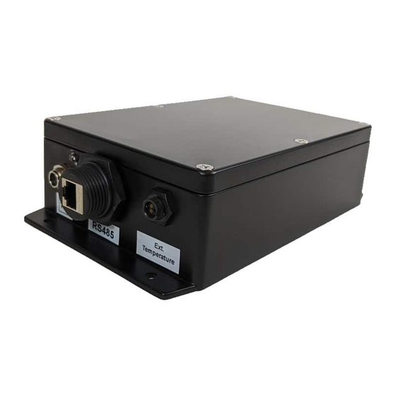
3.2.1 RTU RS485 CONFIGURATION RS485 cabling configuration is shown in the diagrams and table 3-1 below. Bottom View Name Type Description 3.3V Reference potential 3.3V Reference Voltage Reference potential Local device ground UART_TX Digital Output Firmware update interface B (D-) Bus In/Out Driver output and receiver input A (D+) -
Page 10: F-901B Modbus Specifications
3.2.2 F-901B MODBUS SPECIFICATIONS • Operates as a slave, half-duplex mode • Modbus functions supported: 0x01 - Read Coils 0x03 - Read Holding Registers 0x04 - Read Input Registers 0x05 - Write Single Coil 0x06 - Write Single Register 0x0F - Write Multiple Coils 0x10 - Write Multiple Registers •... -
Page 11: Holding Registers
3.2.4 HOLDING REGISTERS Mode: Read/Write, size: 16 bits (unsigned) Name Address Default Description PUMP_POWER Internal pump power 0-100% SENSOR_SPAN NONE Sensor span calibration parameter. Calibration formula: SENS_SPAN=SENS_CUR*SENS_SPAN_CUR/SENS_CAL Note: SENS_CAL: expected calibration concentration SENS_SPAN_CUR: Current span value SENS_CUR: Current SENSOR measurement SENSOR_ZERO NONE SENSOR zero calibration parameter... - Page 12 IMPORTANT: backup calibration parameters before performing a calibration. A calibration will overwrite the factory calibration parameter in the Holding register. Accusafe Sensor Module User Manual 06/21/2021...
-
Page 13: Section 4 - Calibration
Section 4 - Calibration All units are shipped factory‐calibrated. Over time all sensors require recalibration to compensate for natural sensor sensitivity loss. The performance of a sensor or the whole instrument should be checked occasionally with calibration gas. When there is significant accuracy error in response, calibration may be indicated. -
Page 14: Zero Calibration Procedure
In most cases clean ambient air can be used for zeroing as long as it is known to be free of any interference gases. Some interferences can be eliminated with the use of the provided charcoal scrubber filter shown to the right. This filter attaches to the inlet filter as shown. - Page 15 3) Enter the correct Sensor Slave Address by touching the entry field (circled in the image above) and entering the address number on the pop-up entry screen. For TCP/IP applications, the slave address will be 192.168.1.XX (substitute the Sensor module’s modbus address for “XX”). For RTU applications, the slave address will only be the 2 digit modbus address.
-
Page 16: Span Calibration
9) When the calibration timer has elapsed, a “Calibration Completed” window will be displayed as shown below. Press “OK” to accept then press “EXIT” to return to the main SENSOR CALIBRATION screen. 10) If finished with calibration, select the desired screen from the main toolbar. 4.2 SPAN CALIBRATION SPAN Calibration compensates for sensitivity loss in the gas sensor. - Page 17 3) Enter the correct Sensor Slave Address by touching the entry field (circled in the image below) and entering the address number on the pop-up entry screen. For TCP/IP applications, the slave address will be 192.168.1.XX (substitute the Sensor module’s modbus address for “XX”). For RTU applications, the slave address will only be the 2 digit modbus address.
- Page 18 6) Leave the Calibration in Trigger Mode box indicated by the red arrow above UNTICKED. This option will not apply to most Accusafe applications. 7) Touch the “Next Step” button to advance the cal routine. 8) Connect the CAL GAS supply to the inlet of the sensor module as indicated on the screen shown below.
-
Page 19: Digital Calibration Procedure
10) Once the calibration timer elapses and the verification process is complete, a new window will display “Calibration Completed”. Click OK to accept the calibration and EXIT to return to the main sensor calibration screen. 4.2.2 DIGITAL CALIBRATION PROCEDURE 1) Replace the existing sensor with the pre-calibrated sensor provided by Interscan Corp. (See section 5-1, pg. - Page 20 5) Enter the correct Sensor Slave Address by touching the entry field (circled in red in the image above) and entering the address number on the pop-up entry screen. For TCP/IP applications, the slave address will be 192.168.1.XX (substitute the Sensor module’s modbus address for “XX”).
-
Page 21: Section 5 - Maintenance Of The F-901B
Section 5 - Maintenance of the F-901B 5.1 REPLACING THE GAS SENSOR IMPORTANT: • Make sure you have sufficient ESD (electrostatic discharge) protection before accessing internal components. • Follow the steps below carefully to ensure proper sensor installation. 1) Remove the shorting spring from the new sensor (see image to the right). -
Page 22: Particulate Filter Maintenance
5.2 PARTICULATE FILTER MAINTENANCE The particulate filter should be checked regularly to determine if excess buildup of particulate is present. Interscan recommends quarterly inspections as a starting place. If the filter element shows visible discoloration or dirt collection, it should be replaced. If quarterly maintenance checks consistently reveal heavily packed or clogged filters, more frequent inspection is indicated. -
Page 23: Section 6 - Sensor Module Tester App
Section 6 – Sensor Module Tester App The sensor tester app provides the user with computer access to the sensor module’s Modbus registers with both read and write capability. This is most handy for changing the Modbus address of the sensor module if necessary in a multi- sensor network. The Sensor Tester app is provided on a flash drive labeled “ACCUSAFE APPS”. - Page 24 The Devices list along the left edge of the window should show all the connected devices in the network. If no devices are displayed, do the following to connect to the desired module: • Make sure the TCP/IP radio button is ticked** as shown above (circled in red). •...
- Page 25 Clicking the “Read All” button will then populate the register table with all the current values in the registers as shown below. To access the value in a register now shown on the table, select the register type (dropdown menu at the left of the line circled in red), enter the address number in the “Address”...
-
Page 26: Section 7 - Warranty
Section 7 - Warranty INTERSCAN CORPORATION warrants any ACCUSAFE series instrument and gas sensor to be free from defects in material and workmanship for a period of one year from date of shipment. INTERSCAN CORPORATION’s sole obligation under this warranty is limited to repairing or replacing, at its option, any item covered under this warranty, when such item is returned intact, prepaid to the Factory (or designated service center).
Need help?
Do you have a question about the ACCUSAFE F901B and is the answer not in the manual?
Questions and answers