Table of Contents
Advertisement
Quick Links
Copyright 2014
Teledyne API
OPERATION MANUAL
MODEL 751H
HIGH PERFORMANCE
ZERO AIR GENERATOR
© TELEDYNE API
9970 CARROLL CANYON ROAD
SAN DIEGO, CA 92131-1106 USA
Toll-free Phone:
Phone:
Fax:
Email:
Website:
800-324-5190
+1 858-657-9800
+1 858-657-9816
api-sales@teledyne.com
http://www.teledyne-api.com/
07773B DCN6940
23 July 2014
Advertisement
Table of Contents

Summary of Contents for TELEDYNE API 751H
- Page 1 OPERATION MANUAL MODEL 751H HIGH PERFORMANCE ZERO AIR GENERATOR © TELEDYNE API 9970 CARROLL CANYON ROAD SAN DIEGO, CA 92131-1106 USA Toll-free Phone: 800-324-5190 Phone: +1 858-657-9800 Fax: +1 858-657-9816 Email: api-sales@teledyne.com Website: http://www.teledyne-api.com/ Copyright 2014 07773B DCN6940 Teledyne API...
-
Page 3: About This Manual
ABOUT THIS MANUAL This Model 751H High Performance Zero Air Generator operation manual is comprised of multiple documents as listed below. Part No. Name/Description 07773 Model 751H Manual (this manual) 07839 Model 751H Spare Parts List (Appendix A of this manual) - Page 4 This page intentionally left blank. 07773B DCN6940...
-
Page 5: Safety Messages
NEVER use any gas analyzer to sample combustible gas(es)! Note For Technical Assistance regarding the use and maintenance of this instrument or any other Teledyne API product, contact Teledyne API’s Technical Support Department: Telephone: 800-324-5190 Email: sda_techsupport@teledyne.com or access any of the service options on our website at http://www.teledyne-api.com/... - Page 6 CONSIGNES DE SÉCURITÉ Des consignes de sécurité importantes sont fournies tout au long du présent manuel dans le but d’éviter des blessures corporelles ou d’endommager les instruments. Veuillez lire attentivement ces consignes. Chaque consigne de sécurité est représentée par un pictogramme d’alerte de sécurité; ces pictogrammes se retrouvent dans ce manuel et à...
- Page 7 Product Return All units or components returned to Teledyne API should be properly packed for handling and returned freight prepaid to the nearest designated Service Center. After the repair, the equipment will be returned, freight prepaid.
-
Page 8: Table Of Contents
......................BOUT ANUAL ....................... EVISION ISTORY ......................AFETY ESSAGES 1 INTRODUCTION ..................9 ........................9 REFACE 751H F ......................9 EATURES 2 SPECIFICATIONS AND APPROVALS ........... 11 ....................... 11 PECIFICATIONS ................12 PPROVALS AND ERTIFICATIONS 2.2.1 Safety ......................12 2.2.2 EMC ......................... - Page 9 Final Filter ..................... 38 6 TROUBLESHOOTING ................39 APPENDIX A - S ..................... 1 PARE ARTS APPENDIX B - S ....................1 CHEMATICS LIST OF FIGURES 3-1: 751H S ..................14 IGURE TARTUP ONNECTIONS 4-1: P ......................20 IGURE NEUMATIC IAGRAM 4-2: P ..........................
- Page 10 LIST OF TABLES 2-1: S ........................11 ABLE PECIFICATIONS 4-1: P ..............27 ABLE OWER AND EWPOINT ONDITION NDICATORS 5-1: M ...................... 29 ABLE AINTENANCE CHEDULE 6-1: T ......................39 ABLE ROUBLESHOOTING viii 07773B DCN6940...
-
Page 11: Introduction
INTRODUCTION 1.1 Preface The 751H is an excellent source of clean, dry air for dilution calibrators. It also may be used as a source of purge air for permeation tube ovens, zero air for ozone generators, or combustion air for FID analyzers. The 751H has an oil-free and diaphragm-free pump that pushes air through a pre-cooler and water trap that removes moisture, and passes the air through a regenerative, heatless dryer for final drying. - Page 12 Introduction Teledyne API M751H High Performance Zero Air Generator This page intentionally left blank. 07773B DCN6940...
-
Page 13: Specifications And Approvals
SPECIFICATIONS AND APPROVALS Specifications Table 2-1: Specifications Parameter Specification Output 10 SLPM at 30 psig Max delivery pressure 30 psig Dewpoint* < -20°C Dryer Regenerative heatless dryer with lifetime of greater than 5 years <0.025 ppb NO <0.025 ppb <0.025 ppb Output Concentration <0.3 ppb CO <... -
Page 14: Approvals And Certifications
Teledyne API M751H High Performance Zero Air Generator Approvals and Certifications The Teledyne-API Model 751H Zero Air Generator was designed, tested and certified for Safety and Electromagnetic Compatibility (EMC). This section presents the compliance statements for those requirements and directives. For additional certifications, please contract Technical Support at 1-800-324-5190 or sda_techsupport@teledyne.com. -
Page 15: Getting Started
GETTING STARTED This section provides instructions on the proper installation and power up of the 751H. Refer to Figure 4-2 for the instrument layout and Table 2-1 for the specifications. NOTE Due to mounting screws through its case, the 751H is not considered waterproof. -
Page 16: Instrument Panel
Getting Started Teledyne API M751H High Performance Zero Air Generator Instrument Panel Figure 3-1 shows the components in the Model 751H instrument layout that are pertinent to starting up the instrument. Figure 3-1: 751H Startup Connections 07773B DCN6940... -
Page 17: Electrical And Pneumatic Connections
ZERO AIR OUT (1/4” swage-type bulkhead union) - Connect the AIR OUT port of the 751H to the INLET fitting of the Model 700 Calibrator with clean 1/4” TFE tubing. Keep this line as short as possible to minimize pressure drops. . The pressure in this line is adjustable, but should normally be 30 ±... -
Page 18: Power-Up
Storage and Transportation If the 751H will not be used for an extended period of time or will be transported, the following procedure applies: 1. Turn off the 751H. -
Page 19: Expendable Kits (Opt 42A)
Getting Started This shut down process will vent any water that has accumulated in the coalescing filter. It will prevent this water from passing into the 751H in the event that the instrument is inverted during storage or shipment. Expendable Kits (OPT 42A) A one-year supply of replacement particulate filters and consumable scrubber media is available from Teledyne API as Option 42A. - Page 20 Getting Started Teledyne API M751H High Performance Zero Air Generator This page intentionally left blank, 07773B DCN6940...
-
Page 21: Operation
Refer to Figure 4-1 for a diagram of the 751H pneumatic flow. The 751H dries and scrubs ambient air to produce zero air. To accomplish this, first the compressor draws air in through the intake filter and compresses it. At the compressor outlet, the air is under pressure and hot from the compression. -
Page 22: Figure 4-1: Pneumatic Diagram
“DRAIN OUT” HC Scrubber “ZERO AIR OUT” Cooling Coil Filter Pressure Gauge Dewpoint Sensor Figure 4-1: Pneumatic Diagram Figure 4-2 and Figure 4-3 are illustrations of the 751H plan view and a close-up of its instrument panel, respectively. 07773B DCN6940... -
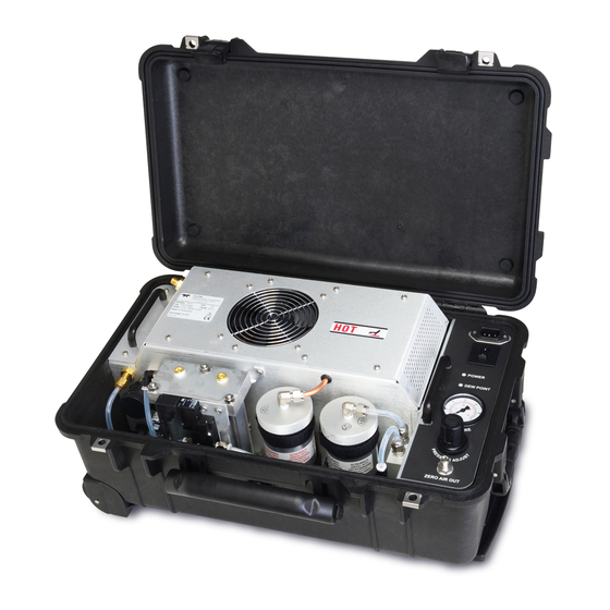
Page 23: Figure 4-2: Plan View
Teledyne API M751H High Performance Zero Air Generator Operation Figure 4-2: Plan View Figure 4-3: Instrument Panel 07773B DCN6940... -
Page 24: Intake Filter
Operation Teledyne API M751H High Performance Zero Air Generator 4.2 Components This section describes the main components and their functions (not all components are visible from the plan view). 4.2.1 Intake Filter The intake filter is a serviceable assembly that houses a screen filter. Maintenance instructions are provided in Section 5 of this manual. -
Page 25: Pressure Relief Valve
The pressure relief valve is a safety device designed to limit the maximum pressure to which the 751H can be subjected. It is set to open at 75-80 psig. This can be quite loud when the valve opens and sounds like steam escaping. This is normal operation and does not mean there is a problem with the unit. -
Page 26: Pressure Regulator
When the 751H is used with the Teledyne API Model 700 Calibrator, the pressure should be between 28 and 32 psig. The Model 700 calibrator requires that its air source be stable and not subject to compressor-induced pressure surges or pressure variations with flow. -
Page 27: No Scrubber
4.2.14 Final Filter The final filter, located adjacent to the instrument panel, retains any particulates released by the 751H. The filter rating is 99.99% removal of 0.1 micron particles. If the filter becomes restricted, it should be replaced. 4.2.15 Pressure Gauge The pressure gauge shows the regulated air pressure available to a calibrator. -
Page 28: Figure 4-4: Control Board Layout
Refer to Figure 4-4 for the layout and to Appendix B for the interconnect and other drawings. The 751H Control PCB is microcontroller based and provides the following functions: • Cycles the four-way valve of the Regenerative Dryer. -
Page 29: Dewpoint Sensor
Teledyne API M751H High Performance Zero Air Generator Operation 4.2.17 Dewpoint Sensor The dewpoint sensor ensures that the Regenerative Dryer maintains a dewpoint less than -20°C (up to the maximum flow rate). This will increase the life of the chemical scrubbers. - Page 30 Operation Teledyne API M751H High Performance Zero Air Generator This page intentionally left blank. 07773B DCN6940...
-
Page 31: Maintenance
MAINTENANCE Schedule WARNING There are high voltages present while the 751H is plugged in. CAUTION The operations outlined in this section are to be performed by qualified maintenance personnel only. Before performing any maintenance, cycle the power on/off and drain any water that may be present (refer to instructions for “Storage and Transportation”... -
Page 32: Maintenance Mode
Placing the 751H in Maintenance Mode will override the fault for 24 hours, allowing time to thoroughly dry the new media before resuming normal operation of the 751H. (In high humidity environments this may take longer). -
Page 33: Replacing The Charcoal Scrubber Media
1. Turn off the 751H and wait for the pressure to go to zero. 2. Remove the 1/4” tubing connected to the top of the scrubber canister. -
Page 34: Replacing The Co Scrubber
9. Replace the TFE tape on the two unions and replace the unions in the cartridge. 10. Reassemble the scrubber and reattach it to the panel. 11. Reconnect the tubing and receptacle. 12. Turn on the 751H and perform a leak check (see Section 5.11). 07773B DCN6940... -
Page 35: Replacing The Hydrocarbon (Hc) Scrubber
Observe that the Heater Relay LED (D8) starts blinking at 11.2 mV (300ºC) and that the thermocouple voltage holds steady. 14. When all traces of water have disappeared from the 751H output, the output may be reconnected to the analyzer. -
Page 36: Servicing The Regenerative Dryer
Wearing a dust mask could be helpful as a preventive measure since the molecular sieve may be dusty. 1. Turn off the 751H and turn on again and remove any water in bowl. 2. Unplug the instrument from electrical service. - Page 37 25. Examine the fit of the columns in the manifold groove one more time. 26. Re-attach the 4-way valve bracket. 27. Return the dryer to the 751H chassis and tighten the four captive screws. 28. Reconnect the two pneumatic fittings and the valve power cord.
-
Page 38: Figure 5-1: Regenerative Dryer
MAINTENANCE Teledyne API M751H High Performance Zero Air Generator Figure 5-1: Regenerative Dryer 07773B DCN6940... -
Page 39: Changing The Regenerative Dryer
5. Attach a new valve, complete with tube fittings and muffler(s). 6. Attach the bracket to the upper manifold. 7. Connect the electric cable and two pneumatic fittings. 8. Re-install the dryer in the 751H chassis and tighten the four captive base screws. 5.11 Leak Check WARNING... -
Page 40: Filter Element Replacement
DFU and pulling the tubing away. 3. Dispose of the used DFU. 4. Reinsert the tubing into each end of the new DFU (Teledyne API P/N FL50), pushing in tightly to secure. 5. Secure the new filter unit into the retainer clip. -
Page 41: Troubleshooting
Teledyne API M751H High Performance Zero Air Generator TROUBLESHOOTING TROUBLESHOOTING This section presents possible problems and their causes and solutions. CAUTION – Avoid Warranty Invalidation Failure to comply with proper anti-Electro-Static Discharge (ESD) handling may void your warranty. For anti-ESD handling instructions please refer to the manual, Fundamentals of ESD, PN 04786, which can be downloaded from our website at http://www.teledyne-api.com under Help Center >... - Page 42 Molecular sieve is contaminated. Replace the molecular sieve. CAUTION THE 751H NOMINAL DELIVERY PRESSURE IS 30 PSIG. NEVER SET THE DELIVERY PRESSURE HIGHER THAN 35 PSIG. TO DO SO MAY CAUSE DAMAGE TO THE 751H AND INJURY TO THE OPERATOR. 07773B DCN6940...
- Page 43 APPENDIX A - SPARE PARTS Use of replacement parts other than those supplied by TAPI may result in non- Note compliance with European standard EN 61010-1. Due to the dynamic nature of part numbers, please refer to the Website at Note or call Technical Support at 800-324-5190 for more http://www.teledyne-api.com...
- Page 44 This page intentionally left blank. 07773B DCN6940...
- Page 45 GASKET FOR SCRUBBER CANISTERS 077830100 PCA, CONTROL BOARD, 751H 077990000 PUMP ASSY, 115V/60HZ, 751H 077990100 PUMP ASSY, 230V/50HZ, 751H 078580000 ASSY, WATER DROP VALVE 751H 078600000 ASSY, DRYER RELIEF VALVE 751H 078610000 ASSY, 12VDC FAN 751H 080660000 REGULATOR ASSEMBLY, 751H FL0000007...
- Page 46 This page intentionally left blank. 07773B DCN6940...
-
Page 47: Appendix B - Schematics
APPENDIX B - SCHEMATICS 07773B DCN6940... - Page 48 This page intentionally left blank. 07773B DCN6940...
- Page 49 07773B DCN6940...
Need help?
Do you have a question about the 751H and is the answer not in the manual?
Questions and answers