
Related Manuals for Midea SMK-D140HHN1-3

Summary of Contents for Midea SMK-D140HHN1-3
- Page 1 R410A Commercial Air Conditioners Engineering Data High Temperature Hydro Module SMK -D140HHN1-3...
-
Page 3: Table Of Contents
High Temperature Hydro Module CONTENTS 1 External Appearance .................. 3 2 Nomenclature .................... 3 3 System Schematic ..................4 4 Specifications ..................... 5 5 BOM ......................6 6 Dimensions ....................8 7 Unit Installation ..................15 8 Application Examples ................29 9 Pump Model Selection ................ - Page 4 High Temperature Hydro Module 202003...
-
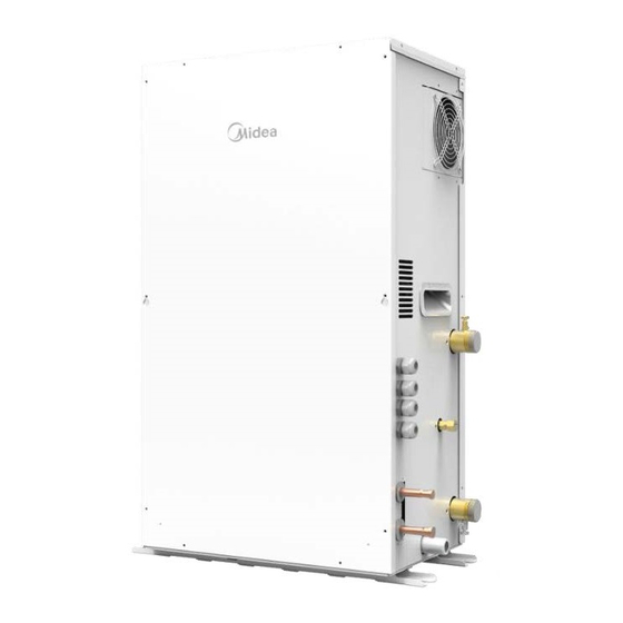
Page 5: External Appearance
1 External Appearance Figure 1.1: Appearance 2 Nomenclature N1-3 Refrigerant N3: R410A & R134A Power Supply: 220-240 V – 50 Hz/60 Hz High Temperature Type Capacity index The capacity in kW multiplied by 10 Used for VRF System Midea hydraulic box 202003... -
Page 6: System Schematic
High Temperature Hydro Module 3 System Schematic The following picture shows a schematic diagram using the High Temperature Hydraulic module and the VR system. The below picture shows a detailed schematic of the VR system using high temperature hydraulic module. Figure 3.1: Hydraulic box connection method 202003... -
Page 7: Specifications
High Temperature Hydro Module 4 Specifications SMK-D140 HHN1-3 Power supply 1P~ 220-240V 50/60Hz Heating Capacity 7/6℃ OAT WIT: 40 / WOT: 45 ºC Working range heating HEAT -20℃~30℃ -20℃~43℃ ambient temperature range 0℃~40℃ sound pressure level water flow rate nominal m³/h m³/h m³/h... -
Page 8: Bom
High Temperature Hydro Module 5 BOM 202003... - Page 9 High Temperature Hydro Module Front panel assembly Electric control box cover assembly Connecting plate Pearl cotton Chassis assembly Pressure pipe clamp Right panel assembly Rubber washer Connecting plate Cable gland Connecting plate Grill Dust plug AC fan Connecting plate Drainage pipe adapter Rear panel assembly Connecting plate assembly Flow Switch (RoHS)
-
Page 10: Dimensions
High Temperature Hydro Module 6 Dimensions 6.1 Structural Dimensions Hydro module unit (top view) 202003... - Page 11 High Temperature Hydro Module 6.2 Center of gravity 202003...
- Page 12 High Temperature Hydro Module 6.3 Installation Space High Temperature Hydraulic module Space for installing piping (on the right side) Space for installation and maintenance (in the front) 202003...
- Page 13 High Temperature Hydro Module 6.4 General Precautions about Installation Site Select an installation site that meets the following conditions: The floor that supports unit weight should be hard enough. The floor should be level to avoid vibration and noise. ...
- Page 14 High Temperature Hydro Module 6.5 General precautions about the Water System Check the following items before continuing installation: Max. hydraulic pressure: 10 bar Max. water temperature: 80 °C Install enough safety devices in the water loops to ensure that the hydraulic pressure does not exceed the maximum operating pressure (10 bar).
- Page 15 High Temperature Hydro Module Propylene Glycol Quality Modification Coefficient Freezing Point Glycol % in degree C Cooling Power Water Water Flow Capacity Modification Resistance Modification Modification 1.000 1.000 1.000 1.000 0.0000 0.976 0.996 1.071 1.000 -3.000 0.961 0.992 1.189 1.016 -7.000 0.948 0.988...
- Page 16 High Temperature Hydro Module 6.7 Installation Diagram ○ D Liquid pipe (connected to the ODU) ○ E Gas pipe (connected to the ODU) ○ F Water discharge pipe (drainage pan) ○ G Y-shaped filter ○ H Access hole (for charging/discharging refrigerant) ○...
-
Page 17: Unit Installation
High Temperature Hydro Module 7 Unit Installation Notes for installers and service engineers Caution The unit should be installed by professional installation operators. Material selection and installation must confirm with the local legal provisions. To check the interior of the unit, open the top panel, front panel, and rear panel first. After you open these three panels, you can see the main parts of the unit. - Page 18 High Temperature Hydro Module Main parts of the unit Compressor Access hole Discharge temperature sensor Water inlet temperature sensor Plate heat exchanger used by the condenser 11 Liquid pipe temperature sensor at the outlet on the R410A refrigerant side Low pressure sensor Electronic expansion valve on the R410A loop High pressure sensor High pressure switch...
- Page 19 High Temperature Hydro Module R410a flow route R134a flow route Wafer flow Compressor Water inlet temperature sensor Plate heat exchanger used by the condenser Water outlet temperature sensor Electronic expansion valve on the R134a loop Water flow switch Plate heat exchanger used by the evaporator High pressure sensor Electronic expansion valve on the R410A loop Low pressure sensor...
- Page 20 High Temperature Hydro Module Connecting wires Power input High Voltage Signal Low Voltage Signal Communication Cables Magnetic Ring Cable Tie When the external wire enters the interior of the unit through a waterproof cable connector, you need to separate the strong-current cable from the weak-current cable for cabling.
- Page 21 High Temperature Hydro Module Connection for other components CN20 CN21 CN22 CN15 CN17 Y1 Y2 C -PU M P N MSP1 N MSP2 AL Coding Assembly unit Coding Assembly unit Connecting the wired controller Connecting the circulating water pump AC contactor Free electrical signal Connecting the AC contactor for controlling water tanks and water...
- Page 22 High Temperature Hydro Module Wired controller wiring Hydro module CN15 Wired Controller Wires X1 and X2 do not have polarity requirements. Voltage 18 V DC Maximum running current (A) Wiring size (mm2) 2x0.5 Free electrical signal port N1/N2 ...
- Page 23 High Temperature Hydro Module Connection line group for IDU and ODU / MS communication Used to connect IDU and ODU communication and transfer the control signals of the IDU and ODU. Please use the wire with a shield layer and ensure that the shield layer is grounded. For instructions on how to connect the ODU or MS, please see the corresponding manual.
- Page 24 High Temperature Hydro Module The hydraulic module can connect the KNX gateway via D1\D2\E so that the third-party wired controller can control the hydraulic module. In this case, X1 and X2 can be used for check query by connecting or without connecting the wired controller, but cannot be used for control.
- Page 25 High Temperature Hydro Module Reserving Y1/Y2 at port Output control interface of the circulating water pump Output control interface of the water tank and water pump Note: The circulating water pump, water tank and water pump are connected to an external contactor for control. Do not directly connect the water pump. Water pump Voltage...
- Page 26 High Temperature Hydro Module Controlling ports via a three-way valve The three-way valve offers the following two methods, subject to the models sold in the market. For details, see the three- way valve manual. N.O indicates normally open output, while N.C indicates normally closed output. Voltage 220-240V~ Maximum running current (A)
- Page 27 High Temperature Hydro Module To set the temperature at multiple points, connect a third-party thermostat to set different temperature set points. CN22 N MSP1 N MSP2 Voltage 220-240V~ Maximum running current (A) < 0.1 Wiring size (mm 2x0.75 Alarm output signal When the unit fails, a signal can be output to indicate the unit status.
- Page 28 High Temperature Hydro Module Installing the wired controller This unit is equipped with a wired controller, which is used to set, operate, and maintain this unit. Before operating the wired controller, please follow the installation procedures. Notes for installers and service engineers Caution ...
- Page 29 High Temperature Hydro Module ② Fix the rear cover on the wall. Note: Do not excessively tighten the installation screws to prevent rear cover deformation of the wired controller. Back cover Signal switching wires Electrician 202003...
- Page 30 High Temperature Hydro Module ③ Wire the wired controller. Cutting place of lower lower left side left side wire outlet wire outlet ④ Connect the wired controller to the unit. Note: * Do not jam wires during installation 202003...
-
Page 31: Application Examples
High Temperature Hydro Module 8 Application Examples Only heating mode is available and the heating mode operates in water outlet temperature control mode. Hydraulic module Water flow switch Wired controller (Accessory) Y-shaped filter (Accessory) Check valve (Provided on site) Safety valve (Accessory) Water pump (Provided on site. - Page 32 High Temperature Hydro Module On-site settings of the wired controller: HEAT MODE=YES DHW MODE=NON Heat mode is valid. DHW mode is LEAVING WATER invalid. TEMP.=YES Water outlet temperature control is valid. Temperature settings 04:27 27-05-2019 MAIN ° MAIN indicates water outlet temperature Sets the desired water control.
- Page 33 High Temperature Hydro Module Only heating mode is available and the heating mode operates in room temperature control mode. Hydraulic module Water flow switch Wired controller (Accessory) Y-shaped filter (Accessory) Check valve (Provided on site) Safety valve (Accessory) Water pump (Provided on site. For model selection, see page 32.) Drain valve (Provided on site) Water replenishing valve (Provided on site) Water collector (Provided on site)
- Page 34 High Temperature Hydro Module On-site settings of the wired controller: HEAT MODE=YES DHW MODE=NON Heat mode is valid. DHW mode is LEAVING WATER invalid. TEMP.=YES Water outlet temperature control is valid. Temperature settings 04:27 27-05-2019 ROOM ° ROOM indicates room temperature control.
- Page 35 High Temperature Hydro Module Only DHW mode is available. Hydraulic module Water flow switch Wired controller (Accessory) Y-shaped filter (Accessory) Check valve (Provided on site) Safety valve (Accessory) Drain valve (Provided on site) Water expansion tank (Provided on site. For model selection, see page 32.) Water replenishing valve (Provided on site) Water pump (Provided on site.
- Page 36 High Temperature Hydro Module On-site settings of the wired controller: DHW MODE=YES DHW MODE=NON DHW mode is Heat mode is invalid. invalid. Temperature settings 04:27 27-05-2019 ° TANK Sets the desired water tank temperature, ranging from 25 C to 80 C. 202003...
- Page 37 High Temperature Hydro Module Heat Mode and DHW Mode Hydraulic module Water flow switch Wired controller (Accessory) Y-shaped filter (Accessory) Check valve (Provided on site) Safety valve (Accessory) Water pump (Provided on site. For model selection, see page 32.) Drain valve (Provided on site) Water replenishing valve (Provided on site) Water collector (Provided on site) Water expansion tank (Provided on site.
- Page 38 High Temperature Hydro Module On-site settings of the wired controller: DHW MODE=YES DHW MODE=YES DHW mode is Heat mode is invalid. invalid. Temperature settings 04:27 27-05-2019 MAIN ° ° TANK Sets the desired Water outlet water tank temperature Sets the desired temperature.
- Page 39 High Temperature Hydro Module Only heating mode is available and there are multiple set points for heating mode. Notes for installers and service engineers Caution When one hydraulic module is connected to multiple terminals that have different temperature requirements (such as the floor heating device, fan coil unit, and radiator), you need to use the multiple set point function.
- Page 40 High Temperature Hydro Module Enabling the multiple set point of the wired controller: When only heating mode is available, the settings are the same as those described above. Multiple set point settings are as follows: multiple setpoint1=ON: Enable multiple set point 1;...
- Page 41 High Temperature Hydro Module Group control Notes for installers and service engineers Caution When multiple hydraulic modules heat water for one water tank, the group control function of the hydraulic module should be used. The group control function is only valid to the DHW mode. Hydraulic module Water flow switch Wired controller (Accessory)
- Page 42 High Temperature Hydro Module To enable the group control function, you need to use the following steps to set the DIP switch on the main board: for the master hydraulic module, turn digit 11; for the slave hydraulic module, turn digit 10. Group control function setting: 00 and 01: Group control function is unavailable.
- Page 43 High Temperature Hydro Module Temperature settings for the wired controller of the master unit: 04:27 27-05-2019 ° TANK Sets the desired water tank temperature, ranging from 25 C to 80 C. Notes for installers and service engineers Caution When the water system side of multiple hydraulic modules are connected in parallel and heat water for a single water tank, you need to set master and slave hydraulic modules.
-
Page 44: Pump Model Selection
High Temperature Hydro Module 9 Pump Model Selection The water pump should meet the flow requirements of the hydraulic module. The rated flow of the hydraulic module is 2.4 m3/h, while the allowed flow range is [1.2, 2.9] m3/h. ... -
Page 45: Selection Of Expansion Tank Volume And Preset Pressure
High Temperature Hydro Module 10 Selection of Expansion Tank Volume and Preset Pressure Calculating the preset pressure of the expansion tank �� ���� = + 0.3 ������ H——The highest point of the water system is higher than the hydraulic module. If ����... -
Page 46: Final Check And Test Run
High Temperature Hydro Module 11 Final Check and Test Run 11.1 Final Check Before closing the switch of the unit, please read the following information: When you complete installation of the unit and have performed all the necessary settings, ensure that all the metal plates are closed. -
Page 47: Piping Design
High Temperature Hydro Module 12 Piping Design R410a flow route R134a flow route Wafer flow Description Compressor R134a to water Plate heat exchanger Electronic expansion valve 1 EEV1 R410a to R134a Plate heat exchanger Electronic expansion valve 2 EEV2 Discharge pipe temperature sensor Suction pipe temperature sensor R134a circle liquid pipe temperature sensor R410a circle liquid pipe temperature sensor... -
Page 48: Wiring Diagram
High Temperature Hydro Module 13 Wiring Diagram Figure 9.1: Power and communication wiring 202003... -
Page 49: Sound Levels
High Temperature Hydro Module 14 Sound Levels Sound pressure level Nom. dB (A) Sound Power Level Nom. dB (A) 202003... - Page 50 High Temperature Hydro Module 31.5 1000 2000 4000 8000 202003...
-
Page 51: Accessories
High Temperature Hydro Module 15 Accessories Installation Manual User Manual Connecting pipe Connected to the water- assembly outlet pipe side (Including safety valve) Water discharge hose Connected to the outlet of the drainage pan Wired controller To control the unit Water temperature For detecting water tank sensor... - Page 52 Ver. 2020-03 Commercial Air Conditioner Division Midea Group Add.: Midea Headquarters Building, 6 Midea Avenue, Shunde, Foshan, Guangdong, China Postal code: 528311 Tel: +86-757-26338346; Fax: +86-757-22390205 cac.midea.com / global.midea.com Note: Product specifications change from time to time as product improvements and developments are released and may vary from those in this...
Need help?
Do you have a question about the SMK-D140HHN1-3 and is the answer not in the manual?
Questions and answers