Table of Contents
Advertisement
Quick Links
Advertisement
Table of Contents

Related Manuals for Sonic SCS-60

Summary of Contents for Sonic SCS-60
- Page 1 Model SCS-60 Scanning Sonar Operation Manual Ver.5.00E Rev. 0...
- Page 2 <MEMO>...
-
Page 3: Table Of Contents
Contents Contents ................................i Safety and handling instructions ........................iv Safety of the hoist unit ............................vi For the transducer .............................. vi For preventing damage at sea .......................... vi On the battery·electric cell exchange......................vii For the safety operation! How to use the emergency stop ................viii Chapter 1 Outline of Basic Operation ...................... - Page 4 5.3.6 TX SYNCRO ....................5-14 5.3.7 TX CYCLE ...................... 5-14 5.3.8 SONAR AREA ....................5-14 5.3.9 SUB AREA 1 ....................5-14 5.3.10 SUB AREA 2 ....................5-14 5.3.11 SUB AREA 3 ....................5-14 5.3.12 SUB AREA 4 ....................5-14 5.3.13 TM/RM ......................5-15 5.3.14 DISCRIM ......................
- Page 5 6.7.3 Gate width change ..................6-19 Chapter 7 Operation and Maintenance of the Hoisting System ............... 7-1 7.1 Description of each part of the M-120 hoisting system ........... 7-1 7.2 Hoist control box (C-93 hoisting control box) ............7-4 7.2.1 Hoist control box ....................7-4 7.2.2 Name of each part of the SHC-10 board ............
-
Page 6: Safety And Handling Instructions
Safety and handling instructions In order to use the instrument safely and correctly, fully read and understand this operation manual. Ask our repair service personnel about maintenance of the instrument. Be sure not to have the instrument overhauled by anyone other than qualified repair personnel. - Page 7 Warning Warning at the check of the ship bottom part or the instrument. 1. When you perform the checking at the ship bottom part, be sure to wear a helmet and safety shoes, act in pairs and create a system so as to communicate with each other at any time.
-
Page 8: Safety Of The Hoist Unit
Safety of the hoist unit ・ Ship speed resistance When using the hoisting device, be sure not to exceed the following ship speed resistance of the hoisting device. When used in excess of the ship speed resistance, the hoisting device may be damaged and cause an accident. Ship speed 18 knots resistance... -
Page 9: On The Battery·electric Cell Exchange
2. Transducer storage operation 1) Press the “ascend” key of the hoisting device on the controller and store the transducer. 2) During ascending, an arrowhead “” is indicated in upper right of the screen and the display bar of the hoisting amount is gradually reduced. 3) When the transducer is stored and the hoisting device go es up to the upper limit, the upper limit message is displayed and the hoisting device stops. - Page 10 For the safety operation! How to use the emergency stop Emergency Stop Press both keys of at a Power OFF key same time. Power ON key 何らかの原因で操作が不能になった場合は 、緊急停止を行って下さい。 If the operation is disabled for some reason, execute the emergency stop. Even if the hoist unit is ascending, power supply is shut off by executing the emergency stop.
- Page 11 INTRODUCTION Thank you very much for purchasing our SCS-60 scanning sonar. We have designed and manufactured instruments under strict quality controls for performance and quality, and have accordingly won high levels of satisfaction and confidence from our customers. Since the SCS-60 scanning sonar has the following features, please read this instruction manual carefully and make good use of the fine performance of this instrument.
- Page 12 <MEMO>...
-
Page 13: Chapter 1 Outline Of Basic Operation
Chapter 1 Outline of Basic Operation 1.1 Emergency stop In case of the occurrence of an abnormal situation, such as "power supply not cut off" ), “keys of the controller do not function,” even though you cut off the power ON key ( or “sonar action stopped,”... -
Page 14: Descent And Ascent Of The Transducer
(Note) If you cut the power switch without storing the transducer, the storage operation of the transducer is automatically performed by the "Automatic ascending operation." After storing the transducer up to the upper limit, the power supply is automatically shut off. In addition, when cutting the power supply for safety, cut the power supply after storing the transducer. -
Page 15: Display Screen
1.2.3 Display screen Regarding the layout screen image mode and sub-display of the sonar, there are five types of displays. By switching as needed, these displays can be used effectively. Layout screen image mode 1.Full-screen sonar display 2.Horizontal sonar display 3.Multi-image display 4.Echo sounder display 5.Audio display... - Page 16 <MEMO>...
-
Page 17: Chapter 2 Names And Functions Of The Controller Keys
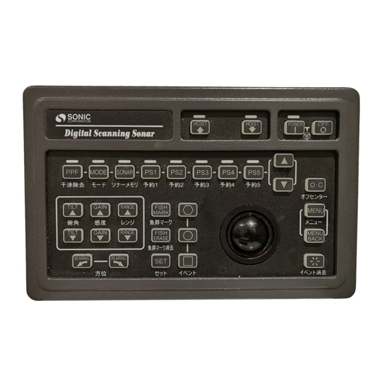
Chapter 2 Names and Functions of the Controller Keys 2.1 Names of keys 17. Ascent key 16. Two-touch keys block 1. Power ON key 18. Descent key 2. Power OFF key 15. Tilt ▲▼ keys 3.Off-center key 4. Menu key 14. -
Page 18: Key Functions
2.2 Key Functions 1. Power ON key The entire system power supply is turned ON. 2. Power OFF key The entire system power supply is turned OFF. Emergency stop key In the event of an emergency requiring instantaneous cutting of the power supply, the entire system power supply is cut by pressing both the power ON key ) and the power OFF key ( ) at the same... - Page 19 12. Bearing mark keys The acoustic sound mark is moved clockwise by the key and counterclockwise by the key. 13. Range keys The display range is changed to one with a longer distance by the key and one with a shorter distance by the key.
- Page 20 c. Sonar memory key This key is used to restore the memory selected from among the STD1 to STD10 internal cards. d. Preset key Each key is used to register one menu item selected from the preset menu. e. UP key This key is used to increase a set value.
-
Page 21: Chapter 3 Marks And Numerical Displays
Chapter 3 Marks and Numerical Displays The following standard marks and numerical values are described in this chapter. 5 External synchronization 2 Bearing mark 6 Internal memory numbers 7 Gain 3 Audio mark 1 Cursor information 10 Transmission indication 8 Tilt 4 Bow line 11 Hoisting amount 9 Range... - Page 22 4. Bow line This line shows the direction in which the ship is going (light blue). 5. External synchronization The external synchronization mode is activated by menu selection in the order of "MENU”–“TX”–“TX SYNCRO”– “EXTERNAL." The mode is indicated as “EXT” on the screen. 6.
- Page 23 15. Heading The ship heading information is shown. If heading information is not input from external equipment, it will not be displayed.* The course of the user’s ship is shown. If course information 16. Course is not input from external equipment, it will not be displayed.* 17.
- Page 24 22. Fish school mark When the fish school mark key is pressed twice, the fish school moving speed and the direction are calculated from the moving distance and the time difference so that the estimated position of the fish school is displayed. 23.
- Page 25 31. Range Ring Distance Mark Shows distance from a vessel to range ring mark. 32. Color Bar This bar consists of 32 colors showing the strength of the echo received. The higher the signal strength is, the redder the indication shows. 33.
- Page 26 34. Tilt information The tilt information currently set is shown. 1.Range 4. Gain 2. Tilt 5. Directional width distance 6. Directional width 7. Tilt line 3. Water depth 8. Tilt scale 10. Distance 9. Multiple mark 1. Range The current range is displayed. 2.
-
Page 27: Chapter 4 Menu
Chapter 4 Menu Many functions that are not used with the controller can be used by opening the menu. These functions enable settings for specific purposes and allow for more functional sonar usage. The menu is operated using the menu key ( ) on the controller and the cross-cursor operated by the track ball. -
Page 28: Settings Of The Menu
4.2 Settings of the MENU 4.2.1 Selecting a setting Place the cross-cursor on the frame of the menu item you want to select, and then press the menu key ( ) to select a setting. Select a setting. Example: When restoring the standard settings Press the menu key ( ) of the controller to open the menu. -
Page 29: Setting A Numeric Value
4.2.2 Setting a numeric value The MENU contains items set by decreasing or increasing numeric values. The setting method is as follows. ▲ Place the cross-cursor on the frame of the up key ( ) in the menu, and then press the menu key ( ) to increase the numeric value. -
Page 30: Returning To The Previous Menus
4.3 Returning to the previous menus 4.3.1 Changing the menu with the menu back key Press the menu back key ( of the controller while the is open. Then, the MENU menu goes back to that of the upper hierarchy that is immediate above the current hierarchy. -
Page 31: Setting Details
4.4 Setting details 4.4.1 Points to note for setting details The sonar system, the change of a set value may result in an adverse effect on system performance. In principle, changes are made by our service engineers. However, if changes are made by yourself, you must be very careful not to influence system performance. - Page 32 <MEMO>...
-
Page 33: Chapter 5 Preset Functions
Chapter 5 Preset Functions 5.1 What is a preset function? With a preset function, you can register a menu item that you use very often but that located in a deep layer as a shortcut, so that you can use such menu easily. This function is referred to as a “preset function.”... -
Page 34: Registering A Function To One Of The Ps1-5 Keys On The Controller
5.2.1 Registering a function to one of the PS1–5 keys on the controller Registration procedure: Similar to menu operations, registration is performed using the cross-cursor and the menu key ( (1) Press the menu key ( ) of the controller and select "PRESET" (2) With the function that you want to register selected by the cursor, press one of the keys of the controller. -
Page 35: Tx Power
Operating the registered preset key The registered preset key is operated by one of the preset keys on the controller and by the UP/DOWN keys ( ) located at the right side of the preset keys. (1) Press the preset key that you want to operate, and then turn ON the red LED located above the preset key. - Page 36 II. Menu items with fixed values Preset menu Set 1 Set 2 Set 3 Set 4 Set 5 Set 6 Set 10 TM/RM RM/HU RM/NU TM/CU NET CAST NET SET DISCRI DISCRIM1 DISCRIM2 DISCRIM3 DISCRIM4 DISCRIM5 DISCRIM6 DISCRIM10 PP FILTER FILTER 1 FILTER 2 FILTER 3...
-
Page 37: Sub Area 1
5.2.2 Registering a function to one of the sub-area selection items on the sonar screen Registration procedure: A preset function can be registered in “SUB AREA 1” or “SUB AREA 2.” As in menu operations, the registration is performed using the cross-cursor and the menu key ( (1) Press the menu key ( ) of the controller to open the menu. - Page 38 (2) Open the preset menu and select item which you want to use. Select "TX PULSE.” (3) Select the function that you want to register using the cross-cursor, and then press the menu key ( When you click "MENU," “TX PULSE” Put the cross-cursor on the item (“DWELL”...
- Page 39 Operating the registered preset key (1) Operation method using the event keys On the reservation screen, the registered function and the present settings are displayed. When you want to change the settings, put the cursor in the frame of the reservation screen, and then press the event key ( ).
- Page 40 (2) Operation method using the menu key and menu back key To change the settings with the menu key ( ) and the menu back key ( place the cross-cursor on the frame of the function on the reservation screen, and then press the menu key ( ) or the menu back key ( I.
- Page 41 II. Menu for setting a fixed value Each time you press the menu key, the setting number goes up. Preset menu Set 1 Set 2 Set 3 Set 4 Set 5 Set 6 Set 10 TM/RM RM/HU RM/NU TM/CU NET CAST NET SET DISCRMI DISCRIM...
- Page 42 5.3 Operations for reservations 5.3.1 NET CAST "NET CAST" is used to store the location of a net. While "NET CAST" is enabled, a red flag mark appears at the location of the ship. The flag moves with the ship tracking as the ship moves.
- Page 43 5.3.2 NET SET This function is for displaying a ring mark according to the fish school echo before a net is cast. This ring mark can also be used to display a predicted circular of the cast net, and to determine the size of the fish school echo. The size of the ring mark can be changed in the "NET LENGTH"...
- Page 44 5.3.3 VRM This function is used to display the VRM of which distance can be changed. < Operation procedure 1> (using this function after it is registered to the two touch key of the controller) Register the “VRM” to any one of the preset keys from (for more details, refer to Section 5.2.1) On the sonar screen, press the preset key in which “VRM”...
- Page 45 VRM distance Net Set mark Net Cast mark Wake A display example of Net Cat, Net Set and VRM 5-13...
- Page 46 5.3.4 TX POWER The “TX POWER” setting can be changed. The setting range is from 0 to 10. When "0" is set to “TX POWER,” transmission will be stopped. When "10" is set, the output will be at its highest. The larger the value, the larger the transmission output, and also the wider the search range becomes.
-
Page 47: Tm/Rm
5.3.13 TM/RM (1) RM/HU In this mode, the bow of the ship always points to the top of the screen. The position of the ship is fixed at the center of the screen. The reflected image of fish schools moves around on the screen relative to the movement of the ship. Normally, the system is operated using these settings for finding a fish school. -
Page 48: Stabilization
5.3.16 STABILIZATION In "STABILIZATION" mode, the system detects the pitching and rolling of the ship and controls the transmitted beam so that the beam will be directed in a certain direction. When you set it to "ON," the " STABILIZATION " function will be activated. The " STABILIZATION "... -
Page 49: Wake Reset
5.3.22 WAKE RESET “WAKE RESET" is used to delete the wake marks drawn on the sonar screen. Once this reset is executed, all of the wake marks already drawn are deleted to back to the stand-by state. Note that once reset is executed, the drawn wake marks can never be displayed again. - Page 50 <MEMO> 5-18...
-
Page 51: Chapter 6 Sonar Area Mode
Chapter 6 Sonar Area Mode 6.1 Sonar area modes There are five sonar area modes. If you fully understand the functions of these sonar area modes and use these functions properly for the intended purposes, you can use the sonar effectively. - Page 52 Change by means of menu operation The sonar area modes can also be changed by menu operation using the cross-cursor and the menu key ( Operation procedure: (1) Press the menu key ( ) to open the menu. (2) Place the cross-cursor over "SUB SCREEN," and then press the menu key ) to open the "SUB SCREEN"...
-
Page 53: Full Screen
6.3 Full screen 6.3.1 Full screen mode The full screen mode enlarges the display of the heading or true bearing images of the horizontal screen using the entire screen. This mode will aid the identification of small response that is detected with a long distance. Full screen mode Note: Neither true motion nor off-center motion are enabled in the full screen mode. -
Page 54: Gain Adjustment
6.3.2 Gain Adjustment The gain in the full screen mode can be adjusted by operating the gain keys ( ) of the controller or by means of menu operation using the cross-cursor and the menu key ( Gain adjustment using the gain keys The gain in the full screen mode can be adjusted by moving the cross-cursor to anywhere on the screen and by pressing a gain key ( ) of the controller. -
Page 55: Tilt Adjustment
6.3.3 Tilt Adjustment The tilt in the full screen mode can be adjusted by operating the tilt keys ( ) of the controller or by menu operation using the cross-cursor and the menu key Tilt adjustment by tilt key operation The tilt in the full screen mode can be adjusted by moving the cross-cursor to anywhere on the screen and by pressing a tilt key ( ) of the controller. -
Page 56: Range Adjustment
6.3.4 Range Adjustment The range in the full screen mode can be adjusted by operating the range keys ( ) of the controller or by menu operation using the cross-cursor and the menu key ( Range adjustment by range key operation The range can be adjusted by moving the cross-cursor to anywhere on the screen and by pressing a range key ( ) of the controller. -
Page 57: Horizontal Screen
6.4 Horizontal screen 6.4.1 Horizontal screen mode The horizontal screen mode displays a 360° horizontal image. SUB AREA 1 SUB AREA 2 SUB AREA 3 SUB AREA 4 Horizontal screen 6.4.2 Gain adjustment The gain in the horizontal screen mode can be adjusted by operating the gain keys ) of the controller or by menu operation using the cross-cursor and the menu key ( Gain adjustment by gain key operation... -
Page 58: Tilt Adjustment
6.4.3 Tilt adjustment The tilt in the horizontal screen mode can be adjusted by operating the tilt keys ( ) of the controller or by menu operation using the cross-cursor and the menu key ( Tilt adjustment by tilt key operation The tilt can be adjusted by moving the cross-cursor to anywhere on the screen and by pressing the tilt keys ( ) of the controller. -
Page 59: Multiple Screens
6.5 Multiple screens 6.5.1 Multi screen mode The multi-screen mode can cut any selected area out from the displayed horizontal screen and display the cut area in the lower part of the screen as a sub-screen. Set mark Tilt display Multi-screen display The multiple screens (sub-screens) can be displayed in the lower part of the screen starting from the left to the right. -
Page 60: Display Method
6.5.2 Display method The multiple screens (sub-screens) can be displayed using the cross-cursor and the setting key ( ) of the controller. Operation procedure (1) Set the mode to the multiple screen mode. (2) Press the setting key ( ) of the controller in the position where you want to display a sub-screen. - Page 61 INPUT TIMING Description The set mark “ ” is displayed in the cross-cursor position at the time of pressing the setting key ( ) and also is Manual displayed on multiple screens. Each time the setting key ( is pressed, the multiple screens are renewed. The multiple screens of areas with the set mark “...
-
Page 62: Tilt Selection/Auto Tilt Mode
6.5.4 Tilt selection/auto tilt mode By combining the tilt selection and the auto tilt mode, the multiple screen mode can be used to find out the width of a fish school or the vertical distribution of a fish school. Method for changing the tilt selection (1) Press the menu key ( ) to open the menu. - Page 63 TILT MODE Description Manual This is for setting the tilt manually. This is for changing the tilt automatically each time the transmission is performed by an angle set using the auto tilt mode. For example, when the tilt is 0°, and 2° is set for the auto tilt mode, Auto the tilt is continually changed each time the transmission is 2°...
- Page 64 Method for changing the auto tilt mode (1) Press the menu key ( ) to open the menu. (2) Place the cross-cursor over "SUB SCREEN,” and then press the menu key ( to open the "SUB SCREEN" menu. (3) Place the cross-cursor over "TILT,” and then press the menu key ( ) to open the "TILT"...
-
Page 65: Echo Sounder Screen
6.6 Echo sounder screen 6.6.1 Echo sounder screen mode The function of the echo sounder screen mode is used when the fish signal input from the outside is displayed together with the sonar image on the same screen. At places without enough space to install both the sonar and echo sounder, this function is useful to view images of the sonar and echo sounder simultaneously. -
Page 66: Gain Adjustment
6.6.2 Gain adjustment The gain in the echo sounder screen mode can be adjusted by operating the gain keys ) of the controller or by menu operation using the cross-cursor and the menu key ( Gain adjustment by gain key operation The gain in the echo sounder screen mode can be adjusted by moving the cross-cursor into the echo sounder screen display area and by pressing the gain keys Gain adjustment by menu operation... -
Page 67: Range Adjustment
6.6.3 Range adjustment The range in the echo sounder screen mode can be adjusted by operating the range keys ( ) of the controller or by menu operation using the cross-cursor and the menu key ( Range adjustment by range key operation The range in the echo sounder screen mode can be adjusted by moving the cross-cursor to the echo sounder screen and by pressing a range key ( Range adjustment by menu operation... -
Page 68: Audio Screen
6.7 Audio screen 6.7.1 Audio screen mode The audio screen mode outputs a sonar image encircled with the audio mark to the audio screen display area. This mode can be used for viewing the history of fish movement. Audio bearing mark Audio screen area... -
Page 69: Gate Width Change
6.7.3 Gate width change There are four types of audio gate widths: narrow (11°), wide (180°), middle (90°), and narrowest (11°; audio marker indication: 0°). You can select a cut range of the audio screen. Operation procedure: (1) Press the menu key ( ) to open the menu. - Page 70 <MEMO> 6-20...
-
Page 71: Chapter 7 Operation And Maintenance Of The Hoisting System
Chapter 7 Operation and Maintenance of the Hoisting System 7.1 Description of each part of the M-120 hoisting system Hoist control box(C-93) Rocker switch Cable gland Gear box Cable fixing brackets Limit switch Guide ring Transducer Seal holder (10) Feed screw (11) Hoisting motor (12) - Page 72 (1) Hoist control box(C-93) Control box that houses the electromagnetic switch, control board, and clinometer (For details, refer to 7.2 Hoist control box.) (2) Rocker switches Power supply ON/OFF switch of the hoisting system with a built-in circuit protector (10A) (For details, refer to 7.2 Hoist control box.) (3) Cable gland With this, by holding the cables of (8) transducer at the outlet of the hoisting pipe, the cables can be fixed and packed.
- Page 73 (9) Seal holder The V gasket is pressed in using the bolts (M8) for maintaining water-tightness. (10) Feed screw Screw for converting the rotation of the (11) hoist motor into hoisting operation (11) Hoisting motor Hoisting drive motor (specifications: 24 V DC; 100W; with a brake) (12) Manual handle This handle is used to perform the ascending or descending operation of the hoisting system when the power is OFF.
-
Page 74: Hoist Control Box (C-93 Hoisting Control Box)
7.2 Hoist control box (C-93 hoisting control box) 7.2.1 Hoist control box Name of each part of the hoist control box Reset button... - Page 75 i. Electromagnetic switch Reversible electromagnetic switch ii. Clinometer For detecting the rolling of the ship and sending information to the transducer, and also for compensating for the ultrasonic transmission beams iii. Thermal relay Hoisting motor protection thermal relay from overcurrent with a set value of 6.6A; when a trip occurs, the switch is raised.
-
Page 76: Name Of Each Part Of The Shc-10 Board
7.2.2 Name of each part of the SHC-10 board (ii) (vii) (iii) (viii) (iv) (vi) (ix) (xii) (xiii) (xiv) (xi) AUTO/MANUAL selecting switch (ii) Manual hoisting switch (iii) +12 V NON-ISO LED (iv) +12 V ISO LED DOWN LED (vi) UP LED (vii) UPPER LMT LED (viii) LOWER LMT LED (ix) HANDLE SW LED... - Page 77 AUTO/MANUAL selecting switch Switch for changing auto/manual operation that is normally set to “AUTO,” with which the hoisting system is made operable using the controller “MANUAL” enables operation using the (ii) manual hoisting switch. Note: Please be careful in that the hoisting system automatically ascends by setting this switch to “AUTO”...
- Page 78 (ix) HANDLE SW LED LED that is turned ON when the manual handle is used; when the LED is ON, hoisting operation using electric power is disabled. When the top cover of the gear box is closed, the LED is OFF. +5 V NON-ISO LED LED that is turned ON when the power of the processor is ON;...
- Page 79 (xiii) Jumper pin for determining contact signal output operation In JP1 setting, the operation of the contact signal output is determined. Please change the setting as necessary. Table: JP1 setting (operation of the contact signal output) JP1 setting Operation of the contact signal output 1-2 shortcut The contact is ON when the hoisting system is at the (before...
-
Page 80: Automatic Ascending
Important: When removing the CB561 cable coating at your site, cut away about 10 mm of wire coating. Any exposed wire length that is not cut away by about 10 mm may cause a contact error or malfunction. 10 mm Figure: CB561 terminal processing 7.2.3 Automatic ascending An automatic ascending circuit for the transducer is installed in this system. -
Page 81: Manual Handle Operation Procedure
7.3 Manual handle operation procedure Warning When using the manual handle operation, please confirm to make the “SWITCH OFF.” If it is kept switch on, this device might suddenly be operated. Manual handle 1) Remove the wingnut that fixes the Descent manual handle and set the handle to the feed screw shaft as shown in the... - Page 82 5) When the work is completed, move the hoisting system to the position of the end in the ascending direction using the manual handle. 6) Loosen (by one turn) the brake release screw (2 spots) of the bottom part of the Hoist Motor, and then make sure that the manual handle is not turned.
-
Page 83: Maintenance And Care Of The Hoisting System
7.4 Maintenance and care of the hoisting system Warning When using the manual handle operation, please confirm to make the “SWITCH OFF.” If it is kept switch on, this device might suddenly be operated. (1) Tightening of the waterproof gasket If water leaks from the hoisting system Hexagon head bolt seal holder, loosen the four M8 bolts of... - Page 84 (3) Replacement of the zinc ring (work in lifting) In order to prevent electrolytic corrosion, a zinc ring is attached to the upper part of the dome. Replace the ring periodically. Change electrolytic corrosion-preventing zinc plates annually. The zinc ring has a two-part structure. Remove two hexagon socket head cap screws to remove the zinc ring.
-
Page 85: Angle Adjustment Of The Clinometer
7.5 Angle adjustment of the clinometer When the hoisting system is mounted on the ship, it is necessary that the “FWD” conforms to the “FWD” direction of the direction of the clinometer in the hoist control box transducer. 2-1) Check for the mounting direction. The connector side of the clinometer is the bow side. - Page 86 <MEMO> 7-16...
-
Page 87: Chapter 8 Connecting A Mouse/Trackball
Chapter 8 Connecting a mouse/trackball The processor of this sonar system is provided with a connector for the use of commercially supplied mice/trackballs. With a mouse/trackball connected to the processor, unique operation not available with the RC-25 is allowed. A mouse/trackball can be connected to the USB port on the connector panel of the processor. -
Page 88: Tilt Adjustment
8.1 Tilt adjustment Tilt adjustment is available using the RC-25 controller. However, connecting a mouse/trackball to the processor allows for tilt adjustment not only from the RC-25 controller but also with the wheel of the mouse/trackball. 8.1.1 Setting method As the operation of a mouse/trackball is enabled only when the mouse/trackball is connected to the processor, the mouse/trackball operation is disabled when the system is shipped. -
Page 89: Tilt Adjustment Method
8.1.2 Tilt adjustment method The tilt can be adjusted upward and downward by turning the wheel as follows. Upward tilt adjustment Downward tilt adjustment... -
Page 90: Event Display
8.2 Event display The event display function is available using the RC-25 controller. However, connecting a mouse/trackball to the processor allows for event display not only from the RC-25 controller but also by using the wheel of the mouse/trackball. 8.2.1 Setting method As the operation of a mouse/trackball is enabled only when the mouse/trackball is connected to the processor, the mouse/trackball operation is disabled when the system is shipped. -
Page 91: Event Display Method
8.2.2 Event display method Place the cross-cursor in any position on the sonar screen, and then click the left button of the mouse/trackball to display event , click the right button to display event , and click the wheel button to display event . - Page 92 Procedure for opening the menu (1) Place the cross-cursor in any position in the sub-screen area (the □ area in the figure below). (2) Click the left button of the mouse/track ball (or press the menu key [ ]) to open the menu.
- Page 93 Procedure for opening the menu in full screen mode (1) Place the cross-cursor in any position at the right end of the display area. (2) Click the left button of the mouse/track ball (or press the menu key [ ]) to open the menu.
- Page 94 <MEMO>...
Need help?
Do you have a question about the SCS-60 and is the answer not in the manual?
Questions and answers