Table of Contents
Advertisement
Quick Links
Link L1500 Series Manual
1.
2.
3.
4.
5.
6.
Images are for illustration only and may differ from components supplied
Link Research Ltd
www.vislink.com
Page 1 of 21
CL140045
Support UK/Europe + (44) 1442 431 410 USA +(1)978 671 5929
Issue F
Link L1500 Series Manual
3
4
5
6
11
14
14
15
16
18
18
19
19
20
21
21
Advertisement
Table of Contents

Related Manuals for Link L1500 Series

Summary of Contents for Link L1500 Series
-
Page 1: Table Of Contents
Link L1500 Series Manual System Description L1500 Transmitter L1500 Display L1500 Menus Transmitter Setup L1500 Connector Interface L1520 Camera Control Module L1500 HD Transmitter Description and Specification Input / Output Connections Mechanical L1520 Camera Controller / Data Receiver – Optional Maintenance &... - Page 2 Document Link L1500 HD Series Systems Manual Issue Date Comments July 07 Working draft – based on LinkHD (L1400) Manual Oct 07 Initial release Oct 07 Minor edits Dec 07 New menu features added for Tx, separate L213x manual created.
-
Page 3: System Description
IRD Receiver For basic operation, connections to the L1500 HD Transmitter unit are HD/SD video, analogue audio and if required an RS232 data link. Power is supplied either via the attached battery plate or external LEMO connector. Images are for illustration only and may differ from components supplied Link Research Ltd www.vislink.com... -
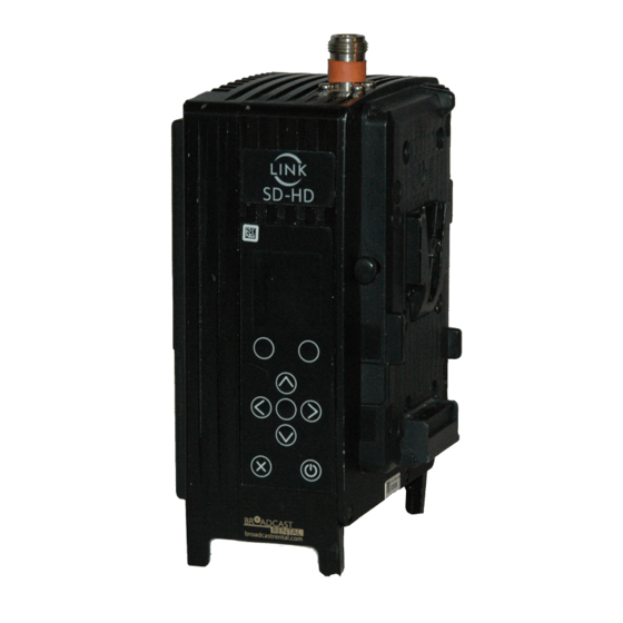
Page 4: L1500 Transmitter
A full list of accessories and cables is given at the end of this document L1500 Transmitter The L1500 Series Encoder/Transmitter is a compact HD/SD MPEG2 Encoder, DVB-T and LMS-T modulator and 100mW output power amplifier (250mW FCC only). LMS-T is a unique robust modulation scheme developed specifically for wireless camera use. -
Page 5: L1500 Display
, transmit frequency and RF modulation mode. Images are for illustration only and may differ from components supplied Link Research Ltd www.vislink.com Support UK/Europe + (44) 1442 431 410 USA +(1)978 671 5929 Page 5 of 21 CL140045 Issue F Link L1500 Series Manual... -
Page 6: L1500 Menus
Some functions are only available in HD mode; these are highlighted in Green shading. Images are for illustration only and may differ from components supplied Link Research Ltd www.vislink.com Support UK/Europe + (44) 1442 431 410 USA +(1)978 671 5929 Page 6 of 21 CL140045 Issue F Link L1500 Series Manual... - Page 7 Sets UHF receiver frequency Images are for illustration only and may differ from components supplied Link Research Ltd www.vislink.com Support UK/Europe + (44) 1442 431 410 USA +(1)978 671 5929 Page 7 of 21 CL140045 Issue F Link L1500 Series Manual...
- Page 8 Sets output level of Test Tone 0-9999 Images are for illustration only and may differ from components supplied Link Research Ltd www.vislink.com Support UK/Europe + (44) 1442 431 410 USA +(1)978 671 5929 Page 8 of 21 CL140045 Issue F Link L1500 Series Manual...
- Page 9 Cust. Support Contact Details Images are for illustration only and may differ from components supplied Link Research Ltd www.vislink.com Support UK/Europe + (44) 1442 431 410 USA +(1)978 671 5929 Page 9 of 21 CL140045 Issue F Link L1500 Series Manual...
- Page 10 Data PID 0100 Images are for illustration only and may differ from components supplied Link Research Ltd www.vislink.com Support UK/Europe + (44) 1442 431 410 USA +(1)978 671 5929 Page 10 of 21 CL140045 Issue F Link L1500 Series Manual...
-
Page 11: Transmitter Setup
Images are for illustration only and may differ from components supplied Link Research Ltd www.vislink.com Support UK/Europe + (44) 1442 431 410 USA +(1)978 671 5929 Page 11 of 21 CL140045 Issue F Link L1500 Series Manual... - Page 12 Due to the improvement that LMS-T has over DVB-T these settings give approximately 50% improvement of bit rates for the same level of ruggedness of the RF link. For example DVB-T 16QAM, 1/32 GI, 1/2 CR gives 12Mbits whereas LMS-T 16QAM gives 18Mbits ASI Operation The L1500 can be used as an MPEG2 HD encoder providing an ASI output.
- Page 13 1 … 2000 ms Link’s interleaving scheme does not touch the encoded bit stream from the transmitter other than to add extra data. It is this extra data that is interleaved. This effect of this is that when a break in RF occurs that is longer than the set burst length, then the break in signal seen at the receiver is the same as the original RF break.
-
Page 14: L1500 Connector Interface
6 way LEMO Ch2 Analogue audio inputs. Line or Mic level 6 way LEMO DATA RS232 connection for Link Control 4 way LEMO External 12V battery supply if rear ‘clip on’ battery is not used. It is also possible to take power from the ‘clip on’... -
Page 15: L1500 Hd Transmitter Description And Specification
50 Hz 37.5 KHz Images are for illustration only and may differ from components supplied Link Research Ltd www.vislink.com Support UK/Europe + (44) 1442 431 410 USA +(1)978 671 5929 Page 15 of 21 CL140045 Issue F Link L1500 Series Manual... -
Page 16: Input / Output Connections
+18dB clipping level (+18db ≡ 0dBFS) Chassis Socket Connector LEMO EEG0B305CLV Mating Cable Plug LEMO FGG0B305CLAD52Z Link Cable Assembly – 2 x XLR3 L0001 Images are for illustration only and may differ from components supplied Link Research Ltd www.vislink.com Support UK/Europe + (44) 1442 431 410 USA +(1)978 671 5929... - Page 17 Power dependent upon frequency of L1510, RF output power and camera control options. Performance is degraded below 11.0V. Chassis Socket Connector LEMO ECG1B304CLV Mating Cable Plug LEMO FGG1B304CLAD62Z Link Cable Assembly– flying leads :- L0003 LEMO Pin Function +12V supply +12V supply vii.
-
Page 18: Mechanical
Serial control data to camera head. Images are for illustration only and may differ from components supplied Link Research Ltd www.vislink.com Support UK/Europe + (44) 1442 431 410 USA +(1)978 671 5929 Page 18 of 21 CL140045 Issue F Link L1500 Series Manual... -
Page 19: Maintenance & Firmware Upgrades
(Advance/System/Restore Defaults). This ensures the correct parameters are loaded for the modules fitted. Images are for illustration only and may differ from components supplied Link Research Ltd www.vislink.com Support UK/Europe + (44) 1442 431 410 USA +(1)978 671 5929 Page 19 of 21 CL140045 Issue F Link L1500 Series Manual... -
Page 20: L1500 Firmware Upgrades
The L1500 unit, including any modules; can be upgraded via the USB port. The required file can be downloaded from the Link Research website and copied onto a suitable USB memory stick after first deleting any previous builds from the memory stick. -
Page 21: L1500 Product Part Numbers
End of Document Images are for illustration only and may differ from components supplied Link Research Ltd www.vislink.com Support UK/Europe + (44) 1442 431 410 USA +(1)978 671 5929 Page 21 of 21 CL140045 Issue F Link L1500 Series Manual...
Need help?
Do you have a question about the L1500 Series and is the answer not in the manual?
Questions and answers