Table of Contents
Advertisement
Quick Links
CONTROLLER
MODEL RC 1T2A
(S/N 10000 and Above)
FIELD SERVICE INSTRUCTIONS
THIS DOCUMENT EMBODIES A PROPRIETARY
DESIGN ORIGINATED BY CONTROL INDUSTRIES,
INC., AND SHALL NOT BE DISCLOSED, USED, OR
DUPLICATED
MANUFACTURING
SPECIFICALLY
INDUSTRIES, INC.
RECEIVER
Rev-1
FOR
PROCUREMENT
PURPOSES,
AUTHORIZED
BY
Control Industries Inc.
614 Central Ave.
Findlay, Ohio 45840
TEL 419-800-0011
FAX 419-500-9015
OR
UNLESS
CONTROL
Advertisement
Table of Contents

Summary of Contents for Control RC-1T2A
- Page 1 RECEIVER CONTROLLER MODEL RC 1T2A (S/N 10000 and Above) FIELD SERVICE INSTRUCTIONS Rev-1 THIS DOCUMENT EMBODIES A PROPRIETARY DESIGN ORIGINATED BY CONTROL INDUSTRIES, INC., AND SHALL NOT BE DISCLOSED, USED, OR DUPLICATED PROCUREMENT MANUFACTURING PURPOSES, UNLESS SPECIFICALLY AUTHORIZED CONTROL INDUSTRIES, INC.
-
Page 2: Theory Of Operation
The receiver is an integrated-circuit design. The sensitivity is adjustable from 1 microvolt to 30 microvolts as desired by the user, permitting a control range of 1 to 20 miles. Receivers are shipped normally adjusted to a sensitivity of 10 microvolts. The unit is designed to operate from 120 volt ±20% 50-60 HZ single phase power. - Page 3 FIG A Functional Diagram...
- Page 4 FIG B INTERCONNECTING WIRING DIAGRAM (with Lightning Suppression Components)
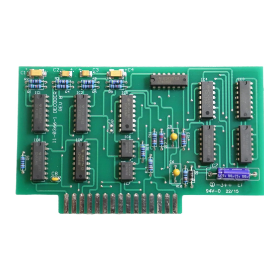
- Page 5 3.1 RADIO FREQUENCY/DECODER CARD (C.I. PART #11-0255) The radio receiver is a superheterodyne design operating at a nominal R.F. frequency within the VHF band of 118 to 136 MHz. An IF frequency of 10.7 MHz is utilized with the bandwidth controlled by a 6-pole crystal lattice filter. This filter establishes nominal -60 db rejection at adjacent channel frequencies of ±25 KHz or more.
- Page 6 In case the load relays have very high coil impedance, keeping the loads energized after K-1 are shut off, the arc suppression networks may be disabled by removing capacitor C-1 K-4 is the heater control relay and has a green LED to indicate when the heater resistor is powered and heating. Fig D...
-
Page 7: Trouble Analysis Chart
Open 5A SLO BLO Fuse Test & Replace fuse with same Relay closures normal type only No output voltage any control line Failure to reset Timer indicator Defective Receiver/Decoder card, Use replacement card and retest. after 5 seconds number 11-0255... -
Page 8: Maintenance Concept
The unit may be maintained readily by technician level personnel. The printed circuit boards are not readily repairable in the field. Return defective printed circuit boards to Control Industries for repair / replacement by the manufacturer. A stock of one each substitute cards should be retained to verify a suspected defective card by simple substitution procedures. -
Page 9: Power Supply
Activated by a signal from the Receiver/Decoder board relays on the relay board close to provide voltage to the control output pins. Relay K1 Controls the Control 1 output. Relay K2 controls the Control 2 Output. Relay K3 controls the Control 3 output. Relay K4 controls the heater resistor. Control output relay activation can be monitored by the red LED’s mounted on the top of the relay board sticking through the plastic board cover. -
Page 10: Timer Function
After the 5 second timer light goes out. The internal timer will start a 15-minute countdown. After 15 minutes the board will reset and open and Control Lines that were activated. The timer will reset to 15 minutes if another selection in made during the countdown period. -
Page 11: Installation
Control and power lines should enter by means of the 1/2-inch conduit entry in the bottom of the unit. A maximum of five conductors is required to complete the installation. -
Page 12: Specifications
LittleFuse MDL 1 9.0 Warranty Information: Control Industries INC. Warranties that the equipment has been manufactured and will perform in accordance with applicable specifications and that any defect in design, materials, or workmanship which may occur during proper and normal use during a period of 1 year from date of installation or 2 years from date of shipment will be corrected by repair or replacement by the manufacturers f.o.b.
Need help?
Do you have a question about the RC-1T2A and is the answer not in the manual?
Questions and answers