
Subscribe to Our Youtube Channel
Summary of Contents for LCS LCS ASC2
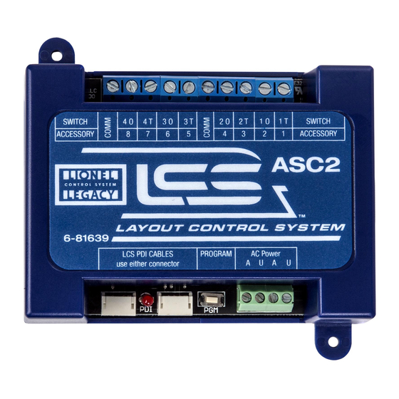
- Page 1 78-1639-250 7/14 SWITCH SWITCH ACCESSORY ACCESSORY LCS PDI CABLES PROGRAM AC Power use either connector Lionel Accessory Switch Controller 2 (ASC2) Owner's Manual...
-
Page 2: Table Of Contents
But until now, combining those parts into a complete system could be a challenge. Lionel’s new Layout Control System or “LCS,” fulfills the LEGACY promise of integrated locomotive and layout control. Table of Contents What is Lionel’s Layout Control System? - Page 3 Controlling switches wired to the ASC2 Routes and the ASC2 Appendix Operation of LEDs Specifications of the LCS ASC2 Accessory configuration examples Switch configuration examples Lionel Limited Warranty Policy & Service The following Lionel marks are used throughout this Owner’s Manual and are protected under law.
-
Page 4: What Is Lionel's Layout Control System
LCS is a modular system, with each product offering unique features. No single LCS product will do everything and not every layout will require every type of LCS device. But a fully realized LCS system will likely include the following: •... -
Page 5: Lcs Asc2 Module
ASC2 module is designed to be connected to track switches and accessories on your model railroad layout. Then you can control these connected switches and accessories from a Lionel hand-held remote or a smart device such as an Apple iPad® and an LCS WiFi module. -
Page 6: Installing Your First Lcs Device
LCS component, please skip ahead to the next section titled “Installing additional LCS devices.” When installing a new LCS system, the process you will follow depends on which (if any) Lionel Command Base is to be connected to your LCS system. Following sections describe starting a new LCS installation with a Legacy Base, a Base-1L or without any command base. -
Page 7: Installing A New Lcs System With A Legacy Base
3. Connect the DB-9 connector of the LCS DB-9 Cable to your Legacy Command Base. 4. Connect the LCS PDI cable end of the LCS DB-9 Cable to either connector on your LCS device, such as an LCS WiFi or LCS SensorTrack or any other Layout Control System product. -
Page 8: Installing A New Lcs System With A Base-1L
3. Connect the DB-9 connector of the LCS DB-9 Cable to your Base-1L. 4. Connect the LCS PDI cable end of the LCS DB-9 Cable to either connector on your LCS device, such as an LCS WiFi or LCS SensorTrack or any other Layout Control System product. -
Page 9: Installing Lcs With Legacy And Trainmaster Command Bases
5. Connect the DB-9 end of the LCS DB-9 Cable to the “Serial Comm” connector of the Legacy Y cable. 6. Connect the LCS PDI cable end of the LCS DB-9 Cable to either connector on your LCS device, such as an LCS WiFi or LCS SensorTrack or any other Layout Control System product. - Page 10 With this setup, you can control Lionel locomotives and Layout Control System products using any combination of LEGACY Remotes, CAB-1L remotes and original CAB-1 remotes. If you have additional LCS devices to install, see “Installing additional LCS devices”. If not, skip ahead to the next section of this manual, “Configuring your LCS Device.”...
-
Page 11: Installing A New Lcs System With No Command Base
Layout Control System can be used without a Lionel Command base. This would be appropriate for a layout which only uses “conventional” or “transformer-controlled” locomotives or a different type of locomotive control system such as DCC. An LCS WiFi is required, as are one other LCS module (such as ASC2 or BPC2). -
Page 12: Installing Additional Lcs Devices
Each new device is connected via LCS PDI cables in a “daisy-chain” fashion (one to the next, and so on). The order of devices in the “chain” is up to you. The only exception is that an LCS WiFi must be the first device in the chain if no Lionel Command Base is present. -
Page 13: Configuring Your Asc2
Configuring Your ASC2 he illustration below shows the name and location of each switch, connector and indicator light on your LCS ASC2 module. The function of each is described on following pages. A – Switch/Accessory terminals should be connected to lights, switches and accessories. -
Page 14: Connect Accessory Transformer To Relay Power Terminals
Figure 9. Connecting two ASC2 modules with LCS PDI cables and parallel external relay power. The ASC2 requires separate external power to operate its internal relays. Multiple ASC2 and/or BPC2 modules can be wired in a daisy-chain fashion as shown above. -
Page 15: Understanding Asc2 Software Configuration
Configuring Your ASC2 Understanding ASC2 Software Configuration Your ASC2 software configuration is a single operation that sets three distinct features: 1. Switch mode vs. Accessory Mode 2. The base address/TMCC ID used to control connected accessories/switches 3. Sub-mode setting. For accessories, the sub-mode chooses between operating an assortment of accessories and/or lights vs. -
Page 16: Switch Vs. Accessory Mode
Configuring Your ASC2 Switch vs. Accessory Mode You cannot mix switch and accessory modes in a single ASC2. In Accessory mode your ASC2 will respond to commands sent to “accessory IDs” from your remote. Up to 8 accessories are supported on a single ASC2. In Switch mode, your ASC2 will respond to commands sent to “switch IDs”... -
Page 17: Configuring Your Asc For Accessory Operation
Configuring & Using ASC2 in Accessory Mode To configure your ASC2 for ACCESSORY Operation: 1. Turn power to your command base and LCS system on. 2. Press and hold the ASC2 PGM button for 1 seconds. The red LED will begin blinking slowly. -
Page 18: Configuring Your Asc For Switch Operation
Configuring & Using ASC2 in Switch Mode To configure your ASC2 for Switch (a.k.a. Turnout) Operation: 1. Turn power to your command base and LCS system on. 2. Press and hold the ASC2 PGM button for 1 seconds. The red LED will begin blinking slowly. -
Page 19: Accessory Examples
Accessory examples his section of the manual describes configuring the ASC2 for operation of up to 8 individual accessories. Your ASC2 must be configured either as a switch controller OR an accessory Note! controller. It cannot control switches and accessories at the same time. Basic on/off accessories and layout lighting can be connected to the Accessory/Switch terminals on the ASC2. -
Page 20: Wiring A Single Basic Accessory
ACCESSORY ASC2 6-81327 Figure 11. An accessory wired to the #1 terminal. The external Power Supply provides operating power LCS PDI CABLES PROGRAM AC Power use either connector for the accessory; the ASC2’s internal relay acts as an on/off switch to control the accessory action. -
Page 21: Wiring And Operating The Floodlight Tower
Ground/U SWITCH SWITCH ACCESSORY ACCESSORY ASC2 6-81327 LCS PDI CABLES PROGRAM AC Power Figure 12. Floodlight Tower wiring example. use either connector To operate the Floodlight Tower. 1. Press ACC on the CAB remote controller. 2. Enter the TMCC ID associated with the accessory connected to terminal #3. (This would be the ASC2's TMCC ID base address +2). -
Page 22: Wiring Multiple Motors Or Lights On The Same Accessory
ACCESSORY ASC2 Figure 13. Here, an ASC2 is connected to control two features of a single accessory. In this example, 6-81327 LCS PDI CABLES PROGRAM AC Power use either connector accessory terminal 7 controls a light and 8 operates a motor. -
Page 23: Wiring And Operating The Sawmill
(bottom view) SWITCH SWITCH ACCESSORY ACCESSORY ASC2 6-81327 LCS PDI CABLES PROGRAM AC Power use either connector Figure 14. Sawmill wiring diagram. Follow these steps to operate the Sawmill. 1. Press ACC on the CAB remote controller. 2. Using your CAB remote controller, enter the TMCC ID associated with the accessory. In this case, that would be the base address +1 (for terminal #2). -
Page 24: Wiring And Operating The Diesel Fueling Station
ACCESSORY ACCESSORY ASC2 Figure 17. Diesel Fueling Station wiring diagram. Operation uses two TMCC ID numbers. 6-81327 LCS PDI CABLES PROGRAM AC Power use either connector Follow these steps to operate the Diesel Fueling Station. 1. Press ACC on the CAB-1L remote controller. -
Page 25: Wiring And Operating Uncoupling Tracks (Asc2 Single-Address Mode)
Uncoupling Track SWITCH SWITCH ACCESSORY ACCESSORY ASC2 6-81327 LCS PDI CABLES PROGRAM AC Power Figure 15. Uncoupling track wiring diagram. use either connector Follow these steps to operate the Uncoupling Track section. 1. Press ACC on the CAB remote controller. - Page 26 Connecting switches to the ASC2 he Accessory Switch Controller is capable of controlling up to four remote switches at a time. Compatible Switches and Switch Controllers include Lionel FasTrack & O27 models, Atlas, Tortoise Switch machines and Z-Stuff switch machines. Note that the ASC2 unit does not supply power to the switches;...
- Page 27 THRU = Green ASC2 6-81327 Figure 19. FasTrack Remote Switch wiring with manual controller lever wired in parallel. LCS PDI CABLES PROGRAM AC Power use either connector Refer to page 18 and set the ASC2 to the momentary power sub-mode. Constant power will...
- Page 28 SWITCH ACCESSORY ACCESSORY lever (optional) ASC2 Switch control Figure 20. Other Lionel switch wiring. Here, two switches are connected to the ASC2's switch #1 lever (optional) 6-81327 and switch #2 terminals. LCS PDI CABLES PROGRAM AC Power use either connector...
- Page 29 Connecting switches to the ASC2 Modifying Lionel O-27 switches for fixed voltage operation O -27 type switches receive their power from variable track voltage. Therefore, track power must be ON in order to operate O-27 switches. If you prefer to operate this type of switch with a fixed voltage power sources (independent of your track power), you need to make the following modifications: First, take the top cover off of the switch by removing the screw.
- Page 30 Refer to page 18 and set the ASC2 to the momentary power sub-mode. Constant power will damage the switch. Power/A Common/Ground/U Through SWITCH SWITCH ACCESSORY ACCESSORY ASC2 Figure 22. Atlas switch wiring. 6-81327 LCS PDI CABLES PROGRAM AC Power use either connector...
- Page 31 If the switch operates in the opposite direction, simply reverse the 1O and 1T wires at the ASC2.. Tortoise Switch Machine Power/A Common/Ground/U Diodes SWITCH SWITCH ACCESSORY ACCESSORY ASC2 6-81327 LCS PDI CABLES PROGRAM AC Power use either connector Figure 24. Tortoise switch machine wiring.
- Page 32 If the switch operates in the opposite direction, simply reverse the 4O and 4T wires at the ASC2.. POWER SUPPLY R AC L SWITCH SWITCH ACCESSORY ACCESSORY ASC2 6-81327 Figure 25. DZ-1000 switch machine wiring. LCS PDI CABLES PROGRAM AC Power use either connector...
- Page 33 Controlling switches wired to the ASC2 o address your switch, press SW and the TMCC ID# of the switch on the CAB remote controller. Be sure to enter the specific ID# corresponding to the ASC2 terminals to which the switch is wired (see Appendix A for additional examples). Once you've addressed a switch, it can be operated using the AUX1 and AUX2 keys on your remote.
- Page 34 Controlling switches wired to the ASC2 Routes and the ASC2 t is sometimes useful to develop set paths for your trains to travel on. For example, on many layouts, trains will travel over a series of switches when passing through a switching yard. A group of switches assigned to a route can be controlled at the press of a button.
- Page 35 Controlling switches wired to the ASC2 Firing routes from a CAB-1L Activating a route will cause your track switches to switch to the appropriate positions, allowing your trains to travel straight or to follow the right or left curve. To activate a route from a CAB-1L: 1.
- Page 36 Red LED on your ASC2 will turn on for 1 second. If it remains on continuously, this indicates a problem with the LCS PDI cabling or your command base. During operation, the Red LED flickers when commands are passing through the LCS PDI bus.
- Page 37 To program your ASC2 for operating up to eight lights and/or accessories on IDs 9-16: 1. Turn power to your command base and LCS system on. 2. Press and hold the ASC2 PGM button for 1 seconds. The red LED will begin blinking slowly.
- Page 38 To program your ASC2 for FasTrack Switch operation on IDs 3, 4, 5 and 6: 1. Turn power to your command base and LCS system on. 2. Press and hold the ASC2 PGM button for 1 seconds. The red LED will begin blinking slowly.
- Page 39 Lionel Limited Warranty Policy & Service his Lionel product, including all mechanical and electrical components, moving parts, motors and structural components, with the exception of LIGHT BULBS, LED’s & TRACTION TIRES are warranted to the original owner-purchaser for a period of one year from the original date of purchase against original defects in materials or workmanship when purchased through a Lionel Authorized Retailer*.
Need help?
Do you have a question about the LCS ASC2 and is the answer not in the manual?
Questions and answers