Advertisement
Quick Links
Advertisement

Related Manuals for Richiger E6910


Summary of Contents for Richiger E6910
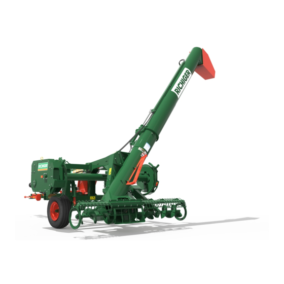
- Page 1 RICHIGER E6910 UNLOADER Operator's Manual...
- Page 2 Operator's Manual This manual Richiger has endeavored to provide the most accurate and clear information on this equipment. Because of efforts to produce the best equipment possible, upgrades and improvements may precede this or subsequent manuals' updates. Therefore, contents of this manual are based on development in effect at the time of publication and are subject to change without notice.
- Page 4 No products shall be returned without prior authorization from RICHIGER MAQUINARIAS S.A. Buyers and their agents shall prepay all transportation charges for the return of such products to RICHIGER MAQUINARIAS S.A or designated service center. There will be no acceptance of any charges for labor and/or parts incidental to the removal and remounting of product repaired or replaced under this warranty.
- Page 5 The following are types of failures which are not attributable to defects in materials and/or workmanship and which are not considered by RICHIGER MAQUINARIAS S.A as part of the warranty extended hereunder. This listing is by way of example and is not intended to be exhaustive: Product suffered damages attributable to accident, abuse, neglect or ignorance.
- Page 6 Machine Description: Model #: Unit #: Date of Purchase: Date of Delivery: Customer Name: Address: City: State: Dealer Name: Address: City: State: The machine detailed above and the Operator's Manual have been received and I understand and have been thoroughly instructed by my dealer about how to operate the machine, Operator's Manual content, equipment care, safe operation &...
- Page 7 Richiger Maquinarias SA Avellaneda 661, S2322BCM Sunchales, Province of Santa Fe, Argentina...
- Page 8 Index Technical specifications page page Dimensions Safety precautions page General indications before actual work page Ground conditions page Initiating labours page Detaching bag from roller page Back to transport mode page page Maintenance Gear oil filling procedure page Lubrication chart page page Lubrication schedule...
- Page 9 Technical specifications All kinds of dry grains (wheat, sorghum, maize, sunflower, soybeans, rice, Materials to be extracted etc.) and pelletized materials Capacity Up to 350 tons/tour (*) Minimum power: Tractor 60 CV 540 rpm PTO revolutions: Extraction system Automatic bag pickup system Working height hydraulically controlled Bag slasher blade Works mechanically and hydraulically...
- Page 10 Dimensions in millimeters Work position Transport position 9 0 3...
- Page 11 Safety precautions Most accidents are caused by human error. Follow all safety procedures. Make sure all people are safely positioned before starting tractor's engine and engaging the PTO. Keep unloader clean and sheltered when not in use. This diminishes risk of deterioration and eventual failure.
- Page 12 General indications before actual work Tractor The tractor used with the E6910 unloader should have no less than 60 HP. Hydraulic circuit can be either open loop or closed loop. PTO stub The PTO drive shaft should not exceed a 360 millimeter (14”) length, measured from end of...
- Page 13 The hydraulic cylinder is used to set the machine's inclination angle and working height. Hoses connect to tractor hydraulic system through 1/2” NPT quick couplings (Fig. 3, “A”). Before connecting hoses to tractor: stop tractor engine and depressurize hydraulic circuit by moving control lever in both directions.
- Page 14 PTO drive shaft Make sure that the correct extremity (i.e., the square bar) of the drive shaft is connected to the tractor's PTO. This is clearly indicated on the shaft itself. CAUTION The PTO drive shaft demands that the operator be attentive and use maximum caution around it. Make sure that protection shieds installed on tractor and shaft do not interfere with each other or with normal shaft movement during work.
-
Page 15: Ground Conditions
Ground conditions were evaluated before bagging the grain. If terrain was not previously prepared it can be loose. The wheels Ground conditions could hit potholes under the bag and tilt to one side.In case the ground is loose, machine height can be increased with hydraulic cylinder. - Page 16 Once the machine rests on the screw jack, hitch it to the tractor drawbar (Fig. 9). Return the screwjack to its horizontal stow position (Fig. 7). Fig. 9 Connect the hydraulic hoses to the tractor's hydraulic system (Fig. 10). Make sure hydraulic quick couplings are well-matched with tractor hydaulic system, as incompatible fittings can restrict flow and cause an oil temperature increase that can damage components.
- Page 17 Remove the short cross auger extension from its transport position (Fig. 13) and attach it to the end of the main auger shaft. Then use pins to mount the corresponding protection grid (Fig. 14). To configure the machine as a 10' bag unloader instead of a 9' bag unloader – the unloader is set up as a 9' machine in factory because transport has to be done under a 9' configuration –...
- Page 18 Three levers on the valve cluster regulate hydraulic flow, as depicted in the diagram below. First and second levers “A” & “B” (which operate the machine's hydraulic cylinders) are mounted on valve sections to the left of the control knob, while third lever “C” (which drives the roller) is mounted to the right of the control knob.
-
Page 19: Machine Clearance
Raising the discharge auger First step in preparing for work is raising the discharge auger. With the tractor's hydraulics turned on, move lever "A" to upward position (Fig. 22). This will raise the auger tube. Before doing that, remove any grain that may have accumulated on the connecting faces as this may prevent correct closure and cause losses through the resulting gap. - Page 20 IMPORTANT The unloader should not be raised or lowered with the hydraulic cylinder if the augers are deep within the grain mass, as this could place undue strain on some components. The correct procedure is to release a few feet of plastic from the roller by counter rotating it hydraulically, advance forward with tractor to extricate the sweep augers from the grain, modify machine clearance with the hydraulic cylinder removing or adding stops as necessary, back the machine once again into the bag to position the augers next to the grain, and reinitiate PTO and roller to continue unloading.
- Page 21 Roller control To turn the roller, lever "C" is used (Fig. 27). Pushing the lever upward turns the roll in the direction that pulls in the bag. Turned up, the lever locks in that position so that operator does not have to hold it continuously during the procedure.
- Page 22 Set up the blade for work Remove the wing nuts, turn blade 90° and replace wing nuts. Then remove blade guard. (Figs. 28, 29 & 30). In this way the blade will face the incoming bag. Fig. 28 Fig. 29 Fig.
- Page 23 At this point in time it is convenient to set the approximate speed at which the roller will work. The roller works in the same manner as a winch, pulling in emptied bag plastic and providing advance movement to the tractor/unloader combo. Having already described how the hydraulic commands drive the roller and with the tractor hydraulics operating, it is convenient to begin with the control knob turned completely clockwise (zero movement) and then gradually turn it clockwise to increase rpm's.
- Page 24 Lift the bottom half of the bag bringing it up to the roller. Punch the plastic sheet through each holding stud (Fig. 34) leaving a remainder of 30 or 40 cm to the edge. Notice that the bottom half is one continuous section of plastic that runs along the length of the roller and that the black inner layer of plastic remains visible.
- Page 25 Once the bottom half of the bag has been secured in this manner, bring up the upper half in a similar way, right over the bottom half already tacked to the roller. Proceed to punch the plastic sheet through each stud, starting from the studs at the end of the roller and progressing toward the center.
- Page 26 IMPORTANT There is no need to be overly precise when fastening the bag to the roller. Even though at this stage the plastic may look crumpled and in disarray, it will stretch and straighten after a few turns of the roller. The basic consideration here is having thebottom part of the bag (the part hooked to the roller first) hold some slack relative to the upper part attached last (one or two feet is enough).
- Page 27 Grain extraction procedure Ensure that the tractor's gear case is disengaged and brakes are off. Failure to comply with this can result in a torn bag or mechanical malfunction. The machine is now ready to begin unloading grain. If not done already, connect PTO and take to 500/540 rpm to turn the augers Receiving truck should begin loading grain at the near end of its cargo box so that as the unloader advances collecting grain, it finishes at the far end of the truck.
- Page 28 Setting roller speed To determine proper speed, wait until grain reaches a level that is approximately 10 centimeters (4 inches) below the roller's level and keep it there by adjusting the knob in either direction. This can be verified visually by observing the mass of grain through the cutter blade opening at the top of the bag. If the gap between grain level and pick-up roller grows too close, and grain is being pulled up into the roller with the bag folds, then too much material is accumulating inside the bag than can be discharged.
- Page 29 Aligning machine and bag During work, it is advisable to check direction once in a while and if necessary correct the steering wheel so that the tractor continues to be pulled back in a straight line. It is very important to prevent the sweep auger extremities from touching the bag sidewalls as this could tear the plastic.
- Page 30 Ending grain extraction When the bag is to be closed because work has been completed and the unloader is being taken away, sufficient plastic is unrolled, either hydraulically or by mechanically disengaging the roller, for the bag to be sealed with plastic strips or 2" x 4" boards nailed together. IMPORTANT Whenever grain extraction is ended, either if the unloader will remain with bag attached to continue work later or if it will be towed away, the correct termination sequence is as follows:...
- Page 31 Once all grain possible has been picked up in this way the tractor engine is stopped. For operator safety, it is now necessary to disconnect the sweep augers from the main transmission while still allowing the discharge auger to turn and unload grain. Remove the lock pin from the sweep auger gear case and pull out the coupling gears' handle (Fig.
- Page 32 At this stage the sliding panel or divider that separates the sweep augers from the discharge auger is introduced in corresponding space between auger flights (Fig. 47). Fig. 47 Then the crescent shaped covers are attached to the ends of the divider, thus effectively covering and sealing both openings of the cylinder shaped grain reception chamber (Fig.
- Page 33 The tractor engine is turned on, its PTO is engaged and the last grain remaining in the bag is shoveled into the auxiliary auger by hand (Fig. 50). Once unloading is concluded and engine turned off, the sweep auger coupling gears' handle should be pushed in and the lock pin reinserted, ready for next use. The coupling gears are connected to the drive shaft by means of a flange fitted with shear bolts.
- Page 34 To detach the bag, the roller must turn freely. The E6910 model uses an automatic clutch to connect and Detaching bag from roller disconnect the roller drive, so there is no need at any time to open the transmission's cover to perform this operation.
- Page 35 Go forward with tractor and unloader until all of the used plastic is released from the roller and lies on the ground (Fig. 55). Fig.55 Back to transport mode Reverse the order of previous steps to set up the machine for transport: Raise hydraulic cylinder to its maximum height, clamp all the stops on the cylinder rod and lower again to rest machine on stops.
- Page 36 Maintenance WARNING: Never perform maintenance or lubrication tasks when there are moving parts. Always stop tractor engine and remove the ignition key as an extra precaution. To check for main drive chain slack, remove covers located on front part of frame and discharge auger tube, and adjust idler sprockets if needed.
- Page 37 Gear oil filling procedure A) The driveline case shown in “A” takes about 4 liters of SAE 140 gear oil in two stages. The filling procedure is as follows: Pour in oil until gear case “A” is full. This will require about two liters (slightly over half a gallon) of oil. Leave it standing for about 24 hours, or to speed up the process connect to tractor and drive the transmission for an hour, preferably with the fill plug removed to facilitate air venting.
-
Page 38: Lubrication Chart
Lubrication chart... -
Page 39: Lubrication Schedule
Lubrication schedule Grease zerks (qty) Lubricant Interval in hours U-joints Grease Sliding shafts Apply w/brush Grease PTO shaft Plastic shields Grease Sliding bearing housing Grease Hinge assy. Grease Discharge tube Cylinder bushing Grease Compression springs Apply w/brush Grease Plastic bearing caps Grease Drive shaft Shaft bearing... -
Page 40: Safety Stickers
Safety stickers... - Page 41 Safety stickers...
- Page 46 The grain flow concept The aptitude of different kinds of grain to flow can be approximately determined by the angle formed by the sides of a mound lying on the ground. A steep angle indicates bad grain flow (Fig. 39) whilst a shallow angle indicates a good flow rate (Fig.
- Page 47 General indications Sweep auger efficiency is dependent on the type of grain being unloaded. The highest output measured in tons for efficient operation extracted per hour is obtained with grains that run well. Free running grain results in more efficient auger operation, a higher discharge rate and less stress on mechanical components.
- Page 48 “B” shows the curved shape that the front part of the bag should adopt - Figs. 41 & 42 - in order that the plastic sheet does not come in contact with the sweep augers or their protection grids with risk of ripping open and losing contents.
- Page 49 slow down the operation. The main rule when dealing with difficult, hard flowing grain is to This means lessening the volume of incoming grain, which in turn means slowing down the roller's revolutions per minute. Let us present a practical example applying some of the parameters mentioned above by analyzing an extraction of “difficult”...
- Page 50 Once the bag has been hooked to the roller and the augers are moving, the operator should begin to haul in the bag by gradually turning open the hydraulic flow control valve (with the roller control lever in its upper position). Grain will start coming out of the discharge auger and simultaneously it will start building up inside the bag to form shape “B”...
- Page 51 General indications and safety tips It is important, in order to avoid accidents that affect oneself and others, to be familiar with the operation of agricultural machinery. Therefore, please follow these guidelines: Allow only people with a working knowledge of the machine, controls and safety rules to operate it. Verify that all safety and instructional decals are in place and in good condition.
-
Page 52: Hand Signals
Hand signals Hand signals have been developed to provide a uniform means of communication between workers on the ground and equipment operators. They are especially useful when noise, distance, or language barriers make voice communication difficult. There are eleven recognized hand signals found in ASAE Standard S351. They are illustrated here in figures. Fig. - Page 53 Hand signals Fig. 6 SPEED IT UP. Fig. 7 SLOW IT DOWN. Fig. 8 START THE ENGINE. Fig. 9 STOP THE ENGINE. Clenching your fist, bend your Extend arm straight out to the Move arm in a circle at waist Move your right arm across arm so your hand is at side palm down.
- Page 54 Notes...
Need help?
Do you have a question about the E6910 and is the answer not in the manual?
Questions and answers