Table of Contents
Advertisement
Quick Links
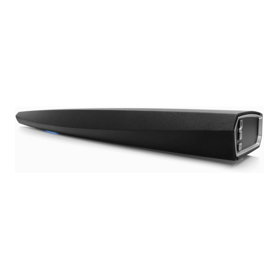
Wireless Soundbar
HEOS Bar
DENON DHT-S716H
h
• For purposes of improvement, specifications and design are subject to change without notice.
• Please use this service manual with referring to the operating instructions without fail.
• Some illustrations using in this service manual are slightly different from the actual set.
Service Manual
Click here!
On-line service parts list
Bar:
http://dmedia.soundunited.com/documents/details/23093
DHT-S716H:
http://dmedia.soundunited.com/documents/details/26094
Online Parts List
(P5 to P7)
WEB owner's manual
EM:
http://manuals.denon.com/HEOSBAR/ALL/EN/index.php
NA:
http://manuals.denon.com/DHTS716H/NA/EN/index.php
EU:
http://manuals.denon.com/DHTS716H/EU/EN/index.php
CAUTION IN SERVICING
ELECTRICAL
MECHANICAL
REPAIR INFORMATION
UPDATING
Please refer to the MODIFICATION NOTICE.
Confidential
Ver. 7
Advertisement
Table of Contents

Related Manuals for Denon DHT-S716H


Summary of Contents for Denon DHT-S716H
- Page 1 Service Manual Ver. 7 Wireless Soundbar HEOS Bar Click here! DENON DHT-S716H On-line service parts list Bar: http://dmedia.soundunited.com/documents/details/23093 DHT-S716H: http://dmedia.soundunited.com/documents/details/26094 Online Parts List (P5 to P7) WEB owner’s manual http://manuals.denon.com/HEOSBAR/ALL/EN/index.php http://manuals.denon.com/DHTS716H/NA/EN/index.php http://manuals.denon.com/DHTS716H/EU/EN/index.php CAUTION IN SERVICING ELECTRICAL MECHANICAL REPAIR INFORMATION UPDATING • For purposes of improvement, specifications and design are subject to change without notice.
-
Page 2: Caution In Servicing
CAUTION IN SERVICING SAFETY PRECAUTIONS NOTE FOR SCHEMATIC DIAGRAM NOTE FOR PARTS LIST INSTRUCTIONS FOR HANDLING SEMICONDUCTORS AND OPTICAL UNIT Online Parts List Accessing the Parts List Logging in to New SDI and Accessing the Parts List Accessing the Part List from the Model Asset Screen PRINTED CIRCUIT BOARDS Parts Table Downloading the Parts List as an Excel File Revision History... -
Page 3: Safety Precautions
SAFETY PRECAUTIONS ◎ Make a safety check after servicing! The following items should be checked for continued protection of the customer and the service Check that all screws, parts and wires removed or disconnected when servicing have been put back technician. -
Page 4: Note For Schematic Diagram
NOTE FOR SCHEMATIC DIAGRAM WARNING: Parts indicated by the z mark have critical characteristics. Use ONLY replacement parts recommended by the manufacturer. CAUTION: Before returning the set to the customer, be sure to carry out either (1) a leakage current check or (2) a line to chassis resistance check. - Page 5 Online Parts List Accessing the Parts List Logging in to New SDI and Accessing the Parts List (1) Click the URL link on the cover of the service manual. (1) Access New SDI from the URL below. Examples of display <http://dmedia.dmglobal.com>...
- Page 6 Accessing the Part List from the Model Asset Screen Downloading the Parts List as an Excel File (1) Display Model Asset from New SDI. (1) Displays the Parts List. Click the Download icon. (2) Click the section displayed as ▼ Link to Part Lists under the model name. NOTE : If the ▼...
- Page 7 SERIAL NUMBER Searching Part Numbers or Ref. Numbers You can search a Parts List for part numbers or Ref. numbers. Serial Number Organization (1) Enter the part number or Ref. number in the search window of the Parts List, and press the search button.
-
Page 8: Schematic Diagrams
ELECTRICAL SCHEMATIC DIAGRAMS SCH01_MAIN(1/12) SCH02_MAIN(2/12) SCH03_MAIN(3/12) SCH04_MAIN(4/12) SCH05_MAIN(5/12) SCH06_MAIN(6/12) SCH07_MAIN(7/12) SCH08_MAIN(8/12) SCH09_MAIN(9/12) SCH10_MAIN(10/12) SCH11_MAIN(11/12) SCH12_MAIN(12/12) SCH13_AMP SCH14_STATUS LED SCH15_IR LED1/2/3/4, KEY PRINTED CIRCUIT BOARDS MAIN IR LED 1 / 2 / 3 / 4, Status LED, KEY, AMP BLOCK DIAGRAM POWER DIAGRAM WIRING DIAGRAM Remote Code Table... - Page 9 SCHEMATIC DIAGRAMS SCH01_MAIN(1/12) HDMI I n HDMI I n HDMI I n HDMI I n HDMI 3 HDMI 4 HDMI 2 HDMI 1 ESD Protector ESD Protector ESD Protector ESD Protector ESD Protector ESD Protector ESD Protector ESD Protector HDMI_RX1P5V HDMI_RX2P5V C332 R172...
- Page 10 SCH02_MAIN(2/12) HDMI_AVDD33RX HDMI_VDD11 3.3V_MN864778A HDMI_AVDD11RX 3.3V_MN864778A 3.3V MN864788A R154 3.3V R503 R164 R165 TP67 0402 HDMI_VDD33 R149 R155 HDMI_RX3_CEC 0402 0402 0402 RX1P5V HDMI_RX1P5V 0402 R150 RX2P5V HDMI_RX2P5V 0402 HDMI_RX2_CEC HDMI_TX1ARCIN TX0ARCIN RX3P5V HDMI_RX3P5V 0402 R151 HDMI_VDD11 R479 VDD11 VDD33 R156 HDMI_RX1_CEC R157...
- Page 11 C203 LED_ACT1 0.1uF 0402 SN74AHC02DR SN74AHC02DR CONNECT_BUTTON_CORE U21D U21C 3.3VDCORE CONNECT OPTION TABLE IRSEL R283 HEOSBAR DHT-S716H LED_ACT2 R534 BAT54C R423 5.1k 100K ※Use a tolerance of ± 1% (F product) for resistance. 0402 SN74AHC02DR SN74AHC02DR 0402 VOL+_BUTTON_CORE VOL+ 3.3VDCORE 3.3VDCORE...
- Page 12 SCH04_MAIN(4/12) TP150 TP151 VOL+ 5VDCORE TP152 VOL- TP153 MUTE 3.3V_EVER 10nF 100nF LMBT3904LT1G MUTE_LED C225 SOT-23 10nF 100nF 0402 0402 3.3V_TAS5754M TP154 100nF TP156 For Vertical TP157 FB14 600 Ohm @ 100MHz SDA3 TP158 600 Ohm @ 100MHz SCL3 TP159 600 Ohm @ 100MHz MDAC_DATA2 TP160...
- Page 13 SCH05_MAIN(5/12) 3.3V_EVER 68nF DETON_OPT DETON_OPT 4.7nF 600R@100MHz 680R 0603 0402 3.3VD 3.3VD 600R@100MHz TP22 TP23 OPT1 10uF 0.1uF 6.3V 100R 10nF 100nF 10uF SPDIF V_OUT OPT_SPDIF TP24 0.1uF 10uF 6.3V 100R 6.3V 3.3V_EVER OPTICAL 0603 R239 74LVC1G125GV SHELD1 0.1uF INPUT 47pF SHELD2 10nF...
- Page 14 SCH06_MAIN(6/12) DSPA1.1V DSPA3.3V VDDEXT_A VDDEXT_A VDDINT_A 600R@100MHz VDDINT_A C560 C561 C204 C205 C206 C207 C208 C209 C210 C211 C212 C213 C214 C215 C216 10uF 10uF 10nF 10nF 10nF 10nF 10nF 10nF 10nF 10nF 10nF 10nF 10nF 10nF 10nF C562 C563 C564 C565 C566...
- Page 15 SCH07_MAIN(7/12) DSPA3.3V SDRAM3_3 SDRAM3_3 SDRAM3_3 600R@100MHz C250 C251 C252 C253 C254 C255 C256 C248 C249 10nF 10nF 10nF 10nF 10nF 10nF 10nF 10uF 10uF ADDR3_Z ADDR3 ADDR0 ADDR0 DATA0 DATA0 DATA3 DATA3_Z 6.3V 6.3V ADDR2_Z ADDR2 ADDR1 ADDR1 DATA1 DATA1 DATA2 DATA2_Z ADDR1_Z...
- Page 16 SCH08_MAIN(8/12) DSPB1.1V VDDINT_B VDDINT_B C140 C159 C141 C142 C143 C144 C145 C146 C147 C148 C149 C150 C151 C152 C153 C154 C155 C156 C184 C185 C186 C187 C188 C189 100nF 10nF 10nF 10nF 10nF 10nF 10nF 10nF 10nF 10nF 10nF 10nF 10nF 10nF 10nF...
- Page 17 SCH09_MAIN(9/12) 3.3V_MN864778A VCCIO 600R@100MHz 10nF 10nF 10nF 10nF 10nF 10nF 10nF 6.3V 1.8V_CPLD 600R@100MHz VCCINT 10nF 10nF 10nF 6.3V SDACDATA SDAC_DATA PLD_SPIDATA SPI-DATA SDACBCK SDAC_BCLK R471 OR_DSPAI_SL0 OR_DSP-A_INSEL0 SDACMCK SDAC_MCLK R472 OR_DSPAI_SL1 OR_DSP-A_INSEL1 DSPBO_DAT2 DSPB_DATO_2 R473 OR_DSPAI_SL2 OR_DSP-A_INSEL2 XMCKIN XMCK0 PLD_SPICLK SPI-CLK DSPBO_DATA1...
- Page 18 SCH10_MAIN(10/12) Close to AIOS connector 3.3VDCORE R373 0402 BIAS_DETECT R374 0402 5.0V_EVER R205 R206 1.1K 620R 0603 0603 600R@100MHz TP68 C362 C363 100nF 10nF R532 5VDA 5VDA PJ3062A TP69 0402 R425 R426 TP70 U32B A-GND 0402 AUX_IN_R 0402 AUX_IN_R R428 TP71 600R@100MHz C376...
- Page 19 R522 TP17 R308 OPTION TABLE 0402 0402 27K4 OR_DSPAI_SLx Main input selector for DSP-A CEC_IN 0402 HEOSBAR DHT-S716H R243 OPEN PCM9211-A ADC(default) R309 LMBT3904LT1G R506 1.8k ※Use a tolerance of ± 1% (F product) for resistance. SOT-23 PCM9211-A DIR BAT54...
- Page 20 SCH12_MAIN(12/12) 5.0V_EVER 5.0V_EVER 3.3V_EVER LD1117AL-33 TP79 TP80 Vout 3.3V_EVER LL4148 400R Vout R261 LL34 C517 C413 SOT-223 C411 C412 C406 C407 C403 C415 100uF C408 C404 0.01uF 100nF C516 C414 0.1uF 22uF 0.01uF 0.01uF 6.3V 0.1uF 0.01uF C402 220uF 100nF 6.3V C401 0.1uF...
- Page 21 SCH13_AMP PVDD24V 750K 150K PVDD24V 0603 0603 750K 150K 0603 0603 P-GND P-GND 470uF 0.1uF P-GND 470uF 0.1uF P-GND GPIO0 P-GND GPIO1 GPIO0 P-GND GPIO2 GPIO1 P-GND MCLK1 0.22uF GPIO2 P-GND SCLK MCLK2 0.22uF SDIN1 SCLK SDIN2 2.2uF 0.01uF 2.2uF 0.01uF 0402 P-GND...
- Page 22 SCH14_STATUS LED 5VDCORE 0.01uF 0.1uF NET WORK _B LED_ACT 2 TP11 NET WORK _R NET WORK _G TP10 IR_OUT IR_Power 39pF 39pF 39pF 5VDCORE MMBT 3906LT1G SOT-23 4.7K 0603 LMBT 3904LT1G LED_ACT 2 180R SOT-23 0603 270R 0603 0603 470R 0603 0603 AO3402...
- Page 23 SCH15_IR LED1/2/3/4, KEY IR LED1 IR LED2 IR LED3 IR LED4 IR_Power IR_Power IR_OUT IR_OUT 120R 120R 120R 120R 120R 120R 1206 1206 1206 1206 1206 1206 120R 120R 1206 1206 LED1 LED2 LED1 LED2 Infrared Infrared LED1 LED2 Infrared Infrared LED1 LED2...
- Page 24 PRINTED CIRCUIT BOARDS MAIN Lead-free Solder When soldering, use the Lead-free Solder (Sn-Ag-Cu). MAIN (A SIDE) C399 C341 C420 C222 C518 C221 C490 C491 C220 C172 C525 C416 R 409 C397 C529 R 317 C398 C342 C219 C528 C395 C409 C343 R 302 C223...
- Page 25 IR LED 1 / 2 / 3 / 4, Status LED, KEY, AMP IR LED1 (A/B SIDE) Status LED (A SIDE) Status LED (B SIDE) IR LED 1 HEO S Bar IR LED 1 Bo a rd T651000004510 V2.0 2016-09-02 HEO S Bar Status LED Board TP 7 T65100000450A...
-
Page 26: Block Diagram
BLOCK DIAGRAM MIC_MUT 3.3V Rev1.0 Remark:2ADI-DSP version, Renesas RX634 LM358A Delayed L-TW/WF Mute,I2C,Fault Delayed C-TW/WF MUTE PCM5100A Delayed R-TW/WF I2S (-192kHz) Delayed R-TW/WF 3.3V 5V Delayed C-TW/WF TAS5756M Delayed L-TW/WF OPT_Det ADCin MPIO_B(AUXOUT) MPO0 PCM9211 for distribution RXIN ERROR Mute,I2C,Fault MPIO_A RXIN MAINOut AUXIN1... -
Page 27: Power Diagram
POWER DIAGRAM HVA for DAMP 5.0V Always on (for LED, Input detection) Always ON 24VDC, 6.5A peak DC(-30V)DC (0.6A) SMPS 3.3V Always on (for MCU, IR sensor, Input detection etc.) 110W MCP16301 LD1117AL-33 CEC Power Enable @HDMI active Enable @CEC active Enable @Normal 5.0V Audio 5.0V @HDMI active... -
Page 28: Wiring Diagram
WIRING DIAGRAM Left 6pin base (black) 6pin base (White) AMP PCBA 2pin base (black) 41pin FFC base 2.4/5G 2.4/5G antenna antenna AC power +24V DC FFC cable 41pin SMPS 2.4G antenna 2pin base 2pin base 2.4G antenna 41pin FFC base Network Main PCBA 2pin base (red) - Page 29 Remote Code Table RC-1212 IR CODE (Kaseikyo Code) DENON code Parity Genre1 Genre2 Data Parity Remote Key Label controller 10 11 12 13 14 15 16 17 18 19 20 21 22 23 24 25 26 27 28 29 30 31 32 33 34 35 36 37 38 39 40 41 42 43 44 45 46 47 48...
- Page 30 MECHANICAL DISASSEMBLY Flowchart 1. GRILL ASSY 2. BAFFLE ASSY 3. AMP PCB 4. WiFi ANTENNA (2.4GHz, 5GHz) 5. MAIN PCB 6. SMPS PCB 7. KEY PCB 8. STATUS LED PCB EXPLODED VIEW SEALING GASKET VIEW OF AN AIR LEAK PREVENTION PACKING VIEW...
- Page 31 DISASSEMBLY Flowchart • Remove each part following the flow below. • Reassemble the removed parts in the reverse order. • Read "SAFETY PRECAUTIONS" before reassembling the removed parts. • If wire bundles are removed or moved during adjustment or part replacement, reshape the wires after completing the work. Failure to shape the wires correctly may cause problems such as noise. •...
- Page 32 Explanatory Photos for DISASSEMBLY 1. GRILL ASSY • For the shooting direction of each photos used in this manual, see the photo below. • A, B, C and D in the photo below indicate the shooting directions of photos. Proceeding : GRILL ASSY •...
- Page 33 2. BAFFLE ASSY 4. WiFi ANTENNA (2.4GHz, 5GHz) Proceeding : GRILL ASSY → BAFFLE ASSY Proceeding : GRILL ASSY → BAFFLE ASSY → WiFi ANTENNA (2.4GHz) (1) Remove the screws. (1) Remove the screws. Press the lock while removing the FFC. When assembling, tighten the center screws first, then work outward.
- Page 34 5. MAIN PCB 6. SMPS PCB Proceeding : GRILL ASSY → BAFFLE ASSY → WiFi ANTENNA → MAIN PCB Proceeding : GRILL ASSY → BAFFLE ASSY → SMPS PCB (1) Remove the Rear Plate. (1) Remove the connector. Remove the screws. View from the bottom (2) Remove the screws.
-
Page 35: Exploded View
EXPLODED VIEW Parts List : Bar: http://dmedia.soundunited.com/documents/details/23093 Parts List : DHT-S716H: http://dmedia.soundunited.com/documents/details/26094 A BAFFLE ASSY : 4, 40, 48 B BOTTOM HOUSING ASSY : 9, 12, 13, 24, 26, 28a, 28b, 28c, 28d, 29, 30, 31, 32, 44, 60, 63... - Page 36 SEALING GASKET VIEW OF AN AIR LEAK PREVENTION BAFFLE ASSY TOP View View from the inside of BAFFLE ASSY Rear Side Rear Side Front Side Front Side E6 x6 BOTTOM HOUSING ASSY TOP View BOTTOM HOUSING ASSY FRONT View Rear Side Front Side View from the inside of GRILLE ASSY Rear Side...
-
Page 37: Packing View
PACKING VIEW Parts List : Bar: http://dmedia.soundunited.com/documents/details/23093 Parts List : DHT-S716H: http://dmedia.soundunited.com/documents/details/26094 UK plug (UK Only) -
Page 38: Troubleshooting
REPAIR INFORMATION TROUBLE SHOOTING LED STATUS 1. The power cannot be turned on 1. Updating 2. No audio output from this unit 2. Updating (Service region settings) (HDMI/Coax/Opt/AUX/Streaming/Bluetooth/USB) 3. No audio output from this unit 3. Updating (Service Release Type) (Streaming) 4. - Page 39 TROUBLE SHOOTING 1. The power cannot be turned on Insert and unplug the AC cable into the outlet Is the front indicator blinking in blue? at intervals of about 5 minutes 2-3 times. Execute Factory Reset. Press and hold the "Bluetooth" button, then insert the AC cable and wait for more than 5 seconds.
- Page 40 2. No audio output from this unit (HDMI/Coax/Opt/AUX/Streaming/Bluetooth/USB) AMP PCB SMPS PCB Check the cable or connector Check the output voltage Check the output voltage and its connection. [J4] 24V Check the FFC cable between the MAIN PCB and The FFC cable is faulty. AMP PCB.
- Page 41 3. No audio output from this unit 5. No audio output from this unit (Streaming) (COAX) Main PCB Is there a connection between the router and this The circuit around [COAX terminal, J7, U10] is Connect router to this unit according to "QSG". Check the input signal unit? faulty.
- Page 42 7. No audio output from this unit 9. No sound from the connected speakers (HDMI IN 1 - 4) Main PCB Is there no sound from any of the connectors from Check whether there is sound from each individu- The circuits around [U24] and the malfunctioning The speakers with no sound are faulty.
- Page 43 10. Cannot connect to the network by wired LAN 11. Cannot connect to the network by wireless LAN Remove the LAN cable and turn the power back Connect the LAN cable correctly and turn the Is the LAN cable connected correctly? Is the LAN cable connected correctly? on.
- Page 44 13. Cannot operate this unit with the remote control unit 14. IR IN is not operating Are you using the supplied remote control unit? Use the supplied remote control unit. The circuit around [JP2, IR2, U34 : 7pin] is faulty. Check the orientation settings.
- Page 45 LED STATUS Status LED Connect in Status LED 1. Updating 5. Factory Reset The following transition occurs during an update. The same occurs in network and USB updates. Press and hold the "Bluetooth" button before inserting the power plug, then insert the power plug while holding down the button and wait for more than 5 seconds.
- Page 46 Status LED Connect in Status LED 8. When connecting to network (Setup Assistant) 10. Standby The following transition occurs during connection to the network. Refer to "QSG". The following transition occurs when this unit switches to standby. Connection estab- When network Network con- Press "Connect"...
- Page 47 NOTE : Enter the file name in double quotation marks. (The file extension is not required.) Service Region File name ・ Windows PC North America "denon-config-locale-set-1" ・ USB flash drive format : Prepare a USB flash drive formatted in FAT16 or FAT32. NOTE: Europe "denon-config-locale-set-2"...
- Page 48 2. Service Release Type settings update procedures Copy the Service Release Type settings from the USB flash drive to this unit. (4) Enter the file name "aios-config-release-type-set-3" and click the Save button. 2.1. Items to Be Prepared NOTE : Enter the file name in double quotation marks. (The file extension is not required.) ・...
- Page 49 3. How to check the firmware version, service region settings and service release type (2) How to check the version of the "HEOS Apps" (1) How to check the version of the HEOS (illustrations below show the HEOS 3 model) Perform the operations below to display the "About"...
- Page 50 UPDATING PROCEDURE AFTER REPLACING THE PCB. PROCEDURE AFTER REPLACING THE U-COM, ETC. FIRMWARE UPDATE PROCEDURE 1. Items necessary for update 2. Updating via Network 3. Updating via USB 4. Work flow for writing firmware after changing network module...
- Page 51 R506 Be sure to update the firmware. HEOSBAR OPEN Be sure to rewrite the service Module Network Module DHT-S716H 5.1k 1.8k region setting. Be sure to rewrite the service See the PCB below. Release Type setting. (2) Be sure to replace the software with the latest version.
-
Page 52: Firmware Update Procedure
FIRMWARE UPDATE PROCEDURE 1. Items necessary for update Items necessary for update are as follows. Offered / not Offered Update Type Needed Part for Update Requirement Standard Service Equipment Purchase from D&M Article code Download from SDI Not offered by D&M Update Smart phone... - Page 53 • Ethernet cable (CAT-5 or greater is recommended) 2.2. Connection of HEOS NOTE: (1) Search for "HEOS by Denon" in the App Store™ or Google Play™ and download the HEOS app for iOS This display is updating two units at the same time.
- Page 54 3. Updating via USB You can update the firmware by downloading the latest version with USB flash drive. Note: When update is complete, the folder name on the USB flash drive changes to 3.1. Connecting to the USB Memory "heos_40.prod.update.done". (1) Preparation To use the files again, delete the ".done"...
- Page 55 4. Work flow for writing firmware after changing network module Change the network module Follow the instructions below to write the Service region settings. "1. Service region settings update procedures" Check the following. Insert the USB flash drive. ・Serial number of this unit ・...
- Page 56 Copyright 2016-2021 D&M Holdings Inc. All rights reserved.
Need help?
Do you have a question about the DHT-S716H and is the answer not in the manual?
Questions and answers