
Subscribe to Our Youtube Channel
Summary of Contents for Coemar DR1
- Page 1 D I S P L A Y R E P L I C A T O R manuale di istruzioni instruction manual 1^ edizione, giugno 2002 edition, june 2002...
-
Page 3: Table Of Contents
9. Interrogating the connected DMX512 universe ,, 27 10. Replicating a connected projector’ s display ,, 28 11. Navigation menu for projector displays replicated by the DR1 ,, 28 12. Simultaneous activation of multiple projector’ s functions ,, 28 13. Inserting an access pin code ‘’... -
Page 4: Packaging
1 test magnet 2. General characteristics When connected to a DMX 512 installation, the DR1 allows the user to access all the internal functions of any compatible projec- tors which are connected. The DR1 is a device designed for technical users and technicians so that they can manipulate projector functions, even whilst pro- jectors are being utilised by the show’... -
Page 5: Section Descriptions
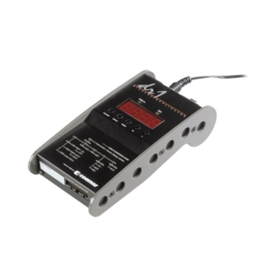
Power and signal connection At one end of the DR1 you will find a power switch and DMX IN and DMX OUT sockets which utilise 5 pin XLR connectors, as well as a socket for connection of the power supply provided with the unit in its packaging. -
Page 6: Dmx512 Signal Connection
English 4. DMX 512 signal connection Via the XLR5 DMX IN socket, the DR1 receives DMX 512 signal which conforms to the international standard for digital DMX 512signal, regulated by the USITT (U.S Institute of Theatre Technology). Connection between the DMX 512 controller and the DR1 follows the standard:... -
Page 7: Mains Connection
5.1 Powering up The DR1 operates at a voltage of between +9/30 V DC at 150 mA. The DR1 should only be connected to mains power via the universal power-supply (100 - 250V~ 50/60 Hz) supplied in the original packaging. Should the power-supply be damaged or fail... -
Page 8: Projectors Able To Be Connected To The Dr1
English 6. Projectors able to be connected to the DR1 DR1 will operate with the following compatible coemar projectors which have the correct software version installed: Panorama Cyc 250: software version from V 2,50 code EP1171 or greater Panorama Cyc 250 C: software version from V 1,60. -
Page 9: Preparing Fixtures To Operate With The Dr1
Attention If a projector’ s id code is set to “0” the projector will not be addressable via the DR1 and so it’ s display will not be able to be ope- rated remotely. -
Page 10: Rapid Guide To Dr1 Menu Navigation
The following sections describe more fully the various functions outlined above. 9. Interrogating the connected DMX 512 universe The first operation to perform when you have connected the DR1 and one or more projectors, is to interrogate the universe to determine exactly how many projectors have been identified. -
Page 11: Replicating A Connected Projector' S Display
At this point, you may commence manipulating a projector’ s parameters via the DR1, which will replicate the projector’ s settings in its display. NOTE: to avoid accidentally altering the parameters of projectors with identical IDs, the DR1 will not allow remote modification. -
Page 12: Inserting An Access Pin Code
3. Press the enter button; the display will show 4. Enter the current pin and press enter; if the old pin is correctly entered, the DR1 will accept the the pin and will allow you to pro- ceed. -
Page 13: Utilising The Sensor Test Pcb
Using the kit and cables provided in the packaging you will be able to quickly monitor the various sensors located in your projector for faults and operation If the DR1. sensor test PCB is not included with your DR1, it may be purchased via the coemar sales network as part number PCO9704 14.1 Connecting the Sensor Test PCB To test the sensors, connect the Sensor Test PCB to the DR1 via the 20 pin socket located at the rear of the DR1 to external “PCB sensor test”... - Page 14 PCB and the other to the magnetic sensor provided with the kit. As before, moving the magnet forward and back will cause the display of the DR1 to alternate if the cabling is undamaged.
- Page 15 PCB and then moving the sensor close to and away from a heat source. By doing so, you should register a change in the temperature displayed on the DR1. Should this not be the case, the cabling is damaged and will require replacement.
- Page 16 Locate the movement sensor within the fix- ture and attach it to the con3 connector of the sensor test PCB. By moving the encoder wheel, the display of the DR1 should display either depending upon the direction of the movement.
-
Page 17: Error Messages
DTER DATA Error The initial parameter settings of the DR1 are either incorrect or corrupt; the DR1 has reloaded its factory default settings. Turn the unit off and on again. Should the error persist, replace the EEPROM replaced. FDER EXPLORATION Error An error has been identified during the exploration procedure. -
Page 18: Technical Characteristics
17. Spare parts All the components of the DR1 are available as replacement spares from your authorised coemar sales agent. Accurate description of the equipment, model number, and type will assist us in providing for your requirements in an efficient and... - Page 19 Inghilterra 46042 Castelgoffredo (Mantova) Italy Tel. 0376/77521 Fax 0376/780657 coemar si riserva il diritto di apportare modifiche senza preavviso. coemar reserves the right to effect modifications without notification manuale istruzioni instruction manual DR1 Display Replicator Sensor Test PCB...
Need help?
Do you have a question about the DR1 and is the answer not in the manual?
Questions and answers