Table of Contents
Advertisement
Quick Links
Advertisement
Table of Contents

Summary of Contents for Chiller VariPro
- Page 1 VariPro Room controller Installation and Operation Manual N03104128 Rev. A...
- Page 2 VariPro Room controller – Installation and Operation Manual Chiller Oy will not assume responsibility for any errors or shortcomings that may appear in this document. The end user is responsible for ensuring that the controller operates appropriately and safely. Working with electric components is subject to permission.
-
Page 3: Table Of Contents
Using the controller menus ..............10 3.3.1 Control modes................11 4 Connections....................12 Connections overview ................12 Connections between the VariPro room controller and the fan coil units ..12 4.2.1 Connection using cables with RJ-9 connectors ......13 4.2.2 Connection using screw connectors..........14 5 Installation .....................15 Installation .....................15... - Page 4 N03104128 Rev. A VariPro Room controller – Installation and Operation Manual Control modes through the bus ..............31 Alarms received through the bus..............31 10 Troubleshooting.....................32 10.1 Troubleshooting..................32 11 Modbus registers ...................33 11.1 Modbus registers ..................33 12 Technical data ....................35 12.1 Technical data ..................35 4 (37) Copyright ©...
-
Page 5: General
Keep the manual for later reference. Guarantee The guarantee for this controller is based on Chiller Oy’s terms of guarantee. The guarantee becomes void, if: • the product is modified or repaired without a written consent from Chiller Oy •... - Page 6 N03104128 Rev. A VariPro Room controller – Installation and Operation Manual 3. Inspect all the delivered controllers carefully. a. If the controllers have transport damages, notify the expeditor and the seller of the controllers. b. Record the transport damages on the bill of freight.
-
Page 7: Safety
N03104128 Rev. A VariPro Room controller – Installation and Operation Manual Safety General safety instructions This controller is designed so that it does not expose people to hazard or risk, provided that: • The controller is installed, operated, and maintained according to the instructions in this manual. - Page 8 N03104128 Rev. A VariPro Room controller – Installation and Operation Manual Prohibited action symbols These symbols are used in warnings and notifications to indicate an action that should not be taken. The prohibited action symbols are shown below. Limited or restricted access...
-
Page 9: Controller Overview
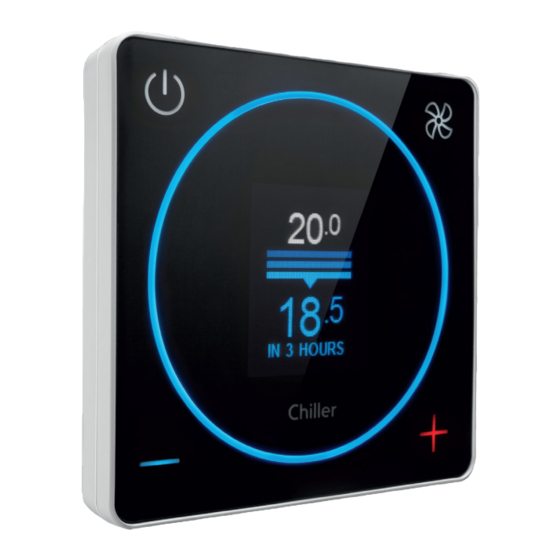
Modbus RTU protocol. Operating principle of the controller Using the VariPro room controller you can set the temperature of a room with 0,5 °C precision. The in-built temperature sensor of the controller continually measures the temperature of a room with 0,1 °C precision. -
Page 10: Using The Controller Menus
VariPro Room controller – Installation and Operation Manual Using the controller menus The menus available with the VariPro room controller vary based on the system configuration. This manual describes all the menus in detail. Figure 1: Using the controller menus... -
Page 11: Control Modes
N03104128 Rev. A VariPro Room controller – Installation and Operation Manual 3.3.1 Control modes • Normal: This is the standard operation mode of the controller. • Away: The controller monitors an expanded dead zone in the Away mode. This helps to save energy. -
Page 12: Connections
VariPro Room controller – Installation and Operation Manual Connections Connections overview The VariPro room controller is intended for use with the VariPro controller card. The controller card is compatible with GRAND VariPro, BOX VariPro and STUDIO VariPro units. Note! Project-specific wiring diagrams are always provided with the fan coil unit. -
Page 13: Connection Using Cables With Rj-9 Connectors
N03104128 Rev. A VariPro Room controller – Installation and Operation Manual 4.2.1 Connection using cables with RJ-9 connectors Note! Always check the wiring when using 4P4C connectors for the connection. Use a straight-through cable, not a twisted cable. Note! Termination (DET A and DET B): Termination is only done for the last unit. -
Page 14: Connection Using Screw Connectors
N03104128 Rev. A VariPro Room controller – Installation and Operation Manual 4.2.2 Connection using screw connectors CAUTION Do not install cabling in a location where it can be exposed to electromagnetic disturbances. Recommended maximum cable length between the controller and the unit or units is 10 m. -
Page 15: Installation
N03104128 Rev. A VariPro Room controller – Installation and Operation Manual Installation Installation DANGER Make sure that the unit is de-energized. 1. Switch off the power supply to the units. 15 (37) Copyright © 2021. All rights reserved. - Page 16 N03104128 Rev. A VariPro Room controller – Installation and Operation Manual 2. Connect the cables to the unit. a. Option 1: Standard communications cable. b. Option 2: Premade RJ-9 quick connector. 3. Attach the wires in the installation box. Note! Quick installation using an RJ-9 cable or screw terminal.
- Page 17 N03104128 Rev. A VariPro Room controller – Installation and Operation Manual 4. Attach the controller’s bottom plate to the installation box. The attaching requires opening the front panel. Open the front panel by pushing the Open button on the bottom of the panel with a thin, pointed object and gently lifting the bottom edge of the control panel.
- Page 18 N03104128 Rev. A VariPro Room controller – Installation and Operation Manual 5. Connect the cables to the controller. a. Option 1: Connect wiring to the bottom plate using a standard communications cable. b. Option 2: Connect the cable directly to the controller using a premade RJ-9 quick connector.
- Page 19 N03104128 Rev. A VariPro Room controller – Installation and Operation Manual 7. Switch on the power supply to the units. Continue to the commissioning stage in Section 6.1 Using the Start Up Wizard. 19 (37) Copyright © 2021. All rights reserved.
-
Page 20: Commissioning
VariPro Room controller – Installation and Operation Manual Commissioning Using the Start Up Wizard Commissioning the VariPro controller is easy: The Start Up Wizard guides you through the first step, and the units detected are then automatically configured. The various control modes can be defined after that. -
Page 21: Scanning Units Manually
N03104128 Rev. A VariPro Room controller – Installation and Operation Manual 3. Verify that all the installed units were found. Select FAN to finish setup. 4. The system is now ready for use. 6.1.1 Scanning units manually A manual scan is needed if units are added to or removed from the system. A manual scan is also recommended in case there is a problem with the connected units that requires troubleshooting. -
Page 22: Identifying The Units
The factory setting is valid when the Modbus ID DIP switches on the VariPro control card are set to 00000000. When using the VariPro controller, changing the unit’s address is not normally required. -
Page 23: Alarms
N03104128 Rev. A VariPro Room controller – Installation and Operation Manual Alarms List of alarms Fan alarm The fan alarm is activated if RPM information is not received from the fan. When the alarm is active, the status of the fan and cooling valve operation is set to 0%. -
Page 24: Resetting The Filter Cleaning Reminder
N03104128 Rev. A VariPro Room controller – Installation and Operation Manual 7.1.2 Resetting the filter cleaning reminder 1. Reset the filter hours by selecting Unit settings→Unit XX→Reset. Note! If there are several units connected to the system, you need to reset the timer for each of the units separately. -
Page 25: Controller Menus
N03104128 Rev. A VariPro Room controller – Installation and Operation Manual Controller menus Main menu Main menu Change the language of the menu. Options are English and Finnish. See Section 8.2 Energy menu / Fan energy See Section 8.3 Service menu See Section 8.4 Unit settings... -
Page 26: Service Menu
N03104128 Rev. A VariPro Room controller – Installation and Operation Manual Service menu The unit connected to the controller Filter status Operating hours of the components Unit settings The units connected to the controller. The number after Unit indicates the unit address. -
Page 27: Unit Menu
N03104128 Rev. A VariPro Room controller – Installation and Operation Manual Unit menu Unit type Unit serial number Reset the filter timer. Set the filter timer limit. Operating hours of the components Operating status of the unit Current fan speed (scaled to the maximum) -
Page 28: Controller Settings
N03104128 Rev. A VariPro Room controller – Installation and Operation Manual Controller settings Controller model Controller software version Controller Modbus address Controller serial number Current temperature setpoint Current room temperature Set the temperature offset. Minimum fan speed on AUTO mode... -
Page 29: Alarms
N03104128 Rev. A VariPro Room controller – Installation and Operation Manual Alarms Active alarm Alarm history Clear alarm history. Testing Note! Use theTesting menu to test individual components of the unit or to open the valves during de-airing. Set fan speed. -
Page 30: Bus Structure
VariPro Room controller – Installation and Operation Manual Bus structure Overview of the bus structure The VariPro controller is equipped with RS-485 interfaces. The controller uses a Modbus RTU protocol, and, in total, 125 controllers can be connected to one branch. -
Page 31: Connecting The Controller In A Building Management System Via A Modbus Protocol
N03104128 Rev. A VariPro Room controller – Installation and Operation Manual Connecting the controller in a building management system via a Modbus protocol 1. Termination is only done for the last unit. Control modes through the bus Various control modes can be set for the controller through the bus (Holding Register 4x00001). -
Page 32: Troubleshooting
N03104128 Rev. A VariPro Room controller – Installation and Operation Manual Troubleshooting 10.1 Troubleshooting Issue Solution Rescanning the system In case of problems, first rescan the system: 1. Select Menu→Unit settings. 2. Select Scan. 3. When the scan is complete, push the Fan button. -
Page 33: Modbus Registers
N03104128 Rev. A VariPro Room controller – Installation and Operation Manual Modbus registers 11.1 Modbus registers Table 1: Register listing for unit with Vari Pro room controller Vari Pro User Interface Register Map v 1.4 Modbus RTU RS485 Baudrate: 9k6, 19k2, 38k4... - Page 34 N03104128 Rev. A VariPro Room controller – Installation and Operation Manual Vari Pro User Interface Register Map v 1.4 Modbus RTU RS485 Baudrate: 9k6, 19k2, 38k4 Parity: None, odd, even Stop bits: 1, 2 Description Read/ Min. Max. Unit Note(s)
-
Page 35: Technical Data
N03104128 Rev. A VariPro Room controller – Installation and Operation Manual Technical data 12.1 Technical data Figure 3: Main dimensions (mm) Property Value Power 24Vdc. < 3VA Setpoint Normal state can be defined, default setting 21 °C. ”Away mode" -> expanded dead zone 0...+15 °C. - Page 36 N03104128 Rev. A VariPro Room controller – Installation and Operation Manual Property Value Precision +-0,5 °C Interfaces Modbus RTU RS-485 for building management systems. Screw connectors (RS-485). RJ-9 quick connector (4P4C). Installation To the mounting box or wall surface. Dimensions (mm)
- Page 37 04300 Tuusula Tel. +358 40 662 0601 Chiller Lahti Chiller Oy Norway info@chiller.fi Rajavartijankatu 9 Tel. +372 506 2986 15170 Lahti ain.kuus@chiller.fi Chiller Norge AS, Oslo Tel. +358 3 876 470 Tel. +47 2207 2940 lahti@chiller.fi salg@chillernorge.no www.chiller.eu/no...
Need help?
Do you have a question about the VariPro and is the answer not in the manual?
Questions and answers