
Summary of Contents for Faraday 8720
- Page 1 User’s Manual 8720 DEVICE PROGRAMMING AND TESTING UNIT F F F F F ARAD ARAD ARAD ARADA A A A A Y Y Y Y Y ARAD P/N 315-033260FA-3 firealarmresources.com...
- Page 2 firealarmresources.com...
-
Page 3: Table Of Contents
Table of Contents Introduct Introduct ..............................Introduct Introduct Introduction ion .............................................. General Description and Features ............3 Getting Started ..................5 Adjusting the LCD and Backlighting ........... 7 P P P P P rogramming rogramming rogramming ................ rogramming ................ - Page 4 DEVICE PROGRAMMING UNIT USERS MANUAL CONTENTS TABLE OF CONTENTS firealarmresources.com...
-
Page 5: Introduct Introduction Ion
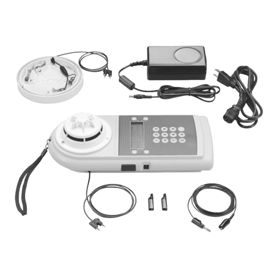
A detector base is integrated into the body of the 8720 for programming intelligent detectors. The 8720 operates from the external power supply or internal batteries. The... - Page 6 JACK SLIDING BATTERY COVER COMPARTMENT RJ11 PRINTER/ UPDATE PORT ALKALINE NiMH USE CABLE 555-134217 ALKALINE NiMH (PROVIDED WITH 8722 LABEL PRINTER) BATTERY SELECTION SWITCH (SHOWN IN NiMH POSITION) BOTTOM OF 8720 Figure 1 The 8720 Device Programming Unit INTRODUCTION firealarmresources.com...
-
Page 7: General Description And Features
8720 ON; pressing the Power Switch a second time turns the 8720 OFF . If the 8720 is operating from batteries and no input is made for two minutes, it will go into a Power Conserva- tion or Sleep Mode. When in the Sleep Mode any keypad entry will Wake or return the 8720 to full operational status without loss of any data previously entered. - Page 8 Attempting to charge Alkaline batteries may damage the batteries or 8720. The 8720 is designed to last for a full day or 4 continuous hours on a single charge. When the batteries are at 20%, the user will be prompted with the display “BATTERIES ARE AT 20%...
-
Page 9: Getting Started
AA batteries are inserted correctly in the battery compartment. • If the 8720 is to be operated from AC, connect the external power supply to the connector provided on the 8720 and then connect it to the wall outlet. - Page 10 Refer to the inside of the Battery Compartment door on the bottom of the 8720 for a description on how to set the correct battery type. •...
-
Page 11: Adjusting The Lcd And Backlighting
The LCD contrast and the display backlighting may be adjusted through the front panel. • While the Main Menu is displayed on the 8720 press the “C” button on the keypad. The display will show numbers that represent the settings for both the LCD and backlight. - Page 12 When the settings are satisfactory, press the “C” key on the keypad and the 8720 display will return to the Main Menu. The 8720 is now set up and ready for use. For instruc- tions on specific operations, refer to the pertinent section of the manual.
-
Page 13: Rogramming
The loop number will only appear if the 8720 has been configured for label printing. The maximum loop setting displayed is 4. If any number greater than 4 entered, “incorrect entry”... - Page 14 | CHAPTER 2 To Program/Test A Compatible Detector: • Align LED in detector with LED symbol on base portion of the 8720 and insert detector into base. • Rotate the detector clockwise until it stops and locks in place. To Remove Detector Head: •...
- Page 15 Once the device is connected, the 8720 will program the address. If the detector or device is programmed successfully, the label printer will print the number of labels selected at setup and and the 8720 will display the message PROGRAMMED OK. 8712 LOOP=1...
-
Page 16: Mpc-1000/Mpc-1500 Detectors And Devices
(position of locating tab) is not important because the devices are not sensitive to polarity. 1000/1500 Detectors and Devices In 1000/1500 systems, the 8720 is used only to set the address of detectors or devices. The other configuration data is sent from the programming tool. -
Page 17: Smoke Detectors
The loop number will only appear if the 8720 has been configured for label printing. The maximum loop setting displayed is 4. If any number greater than 4 is entered, “incorrect entry”... -
Page 18: 8702, 8704, 8701 And 8726
PROGRAM button. The 8720 will prompt the user to insert or connect a device or detector. The 8720 is not equipped with polarity reversal for MPC-1000 and MPC-1500 system devices. If the display searches for a device for longer than two seconds, reverse the polarity of the programming cable. - Page 19 The loop number will appear only if the 8720 has been configured for label printing. Press EXIT to return to the Main Menu.
- Page 20 <EXIT RE-DO> Press EXIT to return to the Main Menu. Press RE-DO to reprogram the detector. When the device is disconnected from the 8720, the display will go into search mode and display INSERT/ CONNECT). 8803 The 8803 must be programmed using cable P/N 555- 133891 that is stored in the cable compartment in the bottom of the 8720.
- Page 21 The loop number will appear only if the 8720 has been configured for label printing. Press EXIT to return to the Main Menu.
- Page 22 DEVICE PROGRAMMING UNIT USER’S MANUAL | CHAPTER 2 PROGRAMMING firealarmresources.com...
-
Page 23: Ing
The loop test menu is available only when the system is set for 6000/7000 and it operates only when the 8720 is powered from AC. Be sure to disconnect the wire between the device and/or detector loop and the system before performing the loop test. - Page 24 • Insert the programming plug in one end of Cable P/N 555-133891 into the red and black jacks in the cable compartment in the bottom of the 8720. • Attach the two alligator clip adaptors provided to the programming plug on the other of cable P/N 555-133891.
- Page 25 DEVICE PROGRAMMING UNIT USER’S MANUAL CHAPTER 3 | the 8720 is set to the MPC-6000/MPC-7000 system. The 8720 will show a display similar to the following: GROUND FAULT = NO INTEL. DEVICES = 121 <SUMMARY <EXIT DETAIL> The top line indicates if there are any ground faults on the loop.
- Page 26 DEVICE PROGRAMMING UNIT USER’S MANUAL | CHAPTER 3 — c t i t i n c t i t i n c t i t i n c t i t i n l l a e l i i n i l l u t n i g i l...
-
Page 27: Testing A Device Or Detector
The 8720 prompts the user to insert or connect a device. (Refer to Figure 2, pages 10-11, to install devices for testing.) When the device is detected, the test is run. The 8720 will display the type of device tested and the address, as shown below: TESTING SUCCESSFUL... - Page 28 6000/7000 At the Main Menu press TEST then press MANUAL. The 8720 will prompt for a device to be connected or a detector to be inserted. (Refer to Figure 2, pages 10-11, to install devices for testing.) When the device or...
- Page 29 DEVICE PROGRAMMING UNIT USER’S MANUAL CHAPTER 3 | Table 3 describes the diagnostic data displayed in the three preceding screens. t l u l i t l l i l a i g i l v i t y t i .
- Page 30 DEVICE PROGRAMMING UNIT USER’S MANUAL | CHAPTER 3 . y l . y l . y l . y l . y l . y l . y l . y l . y l . y l TESTING firealarmresources.com...
-
Page 31: Rint Rinting Labels Ing Labels Ing Labels
Automatic Printing In order to make the 8720 print labels each time a device is programmed, follow the procedure below. Connect the 8720 to the optional printer with programming cable P/N 555-134217 . -
Page 32: Bulk Printing
(COPIES) of the label—from 1 to 9—that you wish to print. When these have been set correctly press the PRINT button. The 8720 will then begin printing the labels and the display will indicate that printing is in progress. An ABORT button is provided to allow the user to cancel the printing operation and return to the bulk printing display. -
Page 33: Maint Maintenance Enance Enance
Maintenance Updating the Firmware The firmware in the 8720 may be updated in the field without disassembly of the unit by connecting a PC to the RJ11 printer/update port and downloading the software to it. The procedure is as follows: Connect the PC with the download software to the update port on the 8720 using cable P/N 600-190704. -
Page 34: Replacing The Batteries
DEVICE PROGRAMMING UNIT USER’S MANUAL | CHAPTER 5 Attempting to recharge non-rechargeable batteries is dangerous and could result in damage to the 8720 or possible explosion. Follow these step to recharge the internal batteries: Check that rechargeable (NiMH) batteries have been installed and that the selection switch inside the battery compartment is set for rechargeables (NiMH). - Page 35 firealarmresources.com...
- Page 36 8 Fernwood Road Florham Park, New Jersey 07932 P/N 315-033260FA-3 firealarmresources.com...
Need help?
Do you have a question about the 8720 and is the answer not in the manual?
Questions and answers