Table of Contents
Advertisement
Quick Links
Advertisement
Table of Contents

Subscribe to Our Youtube Channel
Related Manuals for WattMaster VAV OE391-05

Summary of Contents for WattMaster VAV OE391-05
- Page 1 WattMaster VAV System Operator Interfaces Technical Guide firealarmresources.com...
-
Page 2: Table Of Contents
Toll Free Phone: 866-918-1100 Toll Free Phone: 866-918-1100 Toll Free Phone: 866-918-1100 PH: (816) 505-1100 · FAX: (816) 505-1101 · E-mail: mail@wattmaster.com PH: (816) 505-1100 · FAX: (816) 505-1101 · E-mail: mail@wattmaster.com PH: (816) 505-1100 · FAX: (816) 505-1101 · E-mail: mail@wattmaster.com Visit our web site at www.wattmaster.com... -
Page 3: Introduction
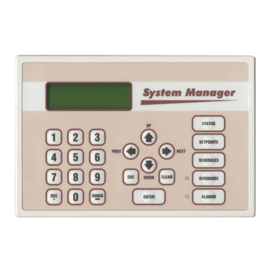
The Modu- 1.63" lar System Manager is designed to be used with the WattMaster VAV Control System. The System Manager is housed in an attractive off- white colored plastic enclosure. The System Manager is equipped with... -
Page 4: System Connections
Technical Guide System Connections Modular Service Tool nications cable can be programmed from any HVAC unit controller on the loop. If this is a Networked System, all controllers on the entire Wether you have a Stand Alone, Interconnected or Networked System, Networked System can be programmed from one HVAC unit control- the Modular Service Tool always connects to an HVAC unit controller ler. -
Page 5: Modular System Manager
Technical Guide Modular System Manager communication and power wiring from the transformer and from the local loop communications terminal on the WMVAV controller or any Power and communications are supplied to the System Manager via a VAVBOX controller’s communication terminal. A class II, 24 VAC modular/pigtail cable that is supplied with the System Manager. -
Page 6: General Programming Information
The Modular Service Tool or the System Manager allow the user to view any temperature or output condition and change any setpoint to In order to configure and program the WattMaster VAV System control- fine tune the operations of the total system. All keypad operations are lers you must have a central operators interface or a personal computer simple and straightforward, utilizing non-cryptic plain English messages. -
Page 7: Service Tool And System Manager
Technical Guide Service Tool And System Manager Entering Unit ID (Address) With both the Modular Service Tool and the Modular System Manager Button Mode Selection Buttons You must enter the ID (Address) of the controller you wish to program Description Modular Service Tool System Manager STATUS... - Page 8 As previously described the System Manager must be configured for the correct mode of operation for your system. Again, there are 3 modes of operation available for the WattMaster VAV System. They are “Stand For “Multiple MGRS Mode” enter the address at which you want this Alone Mode”, “Multiple MGRS Mode”...
- Page 9 Technical Guide System Manager NM & MM Mode Loop Search Once the search is completed the following screen will be displayed. When the System Manager is configured for Network Mode a loop search Loop Search must initially be performed for the System Manager to recognize alarms Finished or overrides.
-
Page 10: Modular Service Tool
Technical Guide General Programming Information System Manager Override Search If you wish to change either Level 1 or Level 2 passcodes please see the instructions that follow. When a space sensor with override option is used with any VAVBOX From the main status screen press "Enter", The following screen will controller or WMVAV controller, the System Manager can determine appear. - Page 11 Technical Guide Modular Service Tool Initialization Screen Modular Service Tool Alarm Search After connecting the Service Tool to the controller with the supplied First, press the “Alarm” key. The Unit Selection screen below will be cable, press the “On” key. The following screen will appear. displayed.
-
Page 12: Programming The Wmvav Controller
Technical Guide Programming The WMVAV Controller Configuration lected as the Controlling Temperature for the WMVAV controller. Avail- able selections are: In order to correctly setup the WMVAV controller you must first con- SUPPLY AIR Supply Air Sensor figure several parameters in regard to the type of HVAC unit and system (Occupied Cooling with you have installed. - Page 13 Technical Guide Configuration Screen #5 Configuration Screen #9 WMVAV Config ID 59 WMVAV Config ID 59 Proof of Flow Switch Relief Pr. Control Installed: Reverse Acting: No [0=NO 1=Yes] [0=NO 1=Yes] If you need proof of airflow before allowing any heating or cooling The Relief Pressure Control described in the previous paragraph can be stages to operate, install a differential pressure switch with a contact configured for reverse acting operation by setting this selection to “Yes”.
- Page 14 Technical Guide Programming The WMVAV Controller Configuration Screen #12 Configuration Screen #16 WMVAV Config ID 59 WMVAV Config ID 59 CO2 Sensor Maximum Broadcast Supply Reading: 2000 PPM Temperature: Enter 0 If No Sensor [0=NO 1=YES] If you install the default CO sensor, it will be a 0-10 VDC device that This enables the WMVAV Controller to send its supply air temperature provides 0-2000 PPM readings.
- Page 15 “Maximum Airflow” position. Re-Heat On/Off Control Of A Re-heat Device Configuration Screen #21 Warm-up Mode On/Off Signal That Causes WattMaster Controlled VAV Boxes To WMVAV Config ID 59 Drive Open to Maximum Airflow Broadcast VAV Boxes Pre-heater...
-
Page 16: Setpoints
Technical Guide Programming The WMVAV Controller Setpoints Setpoint Screen #2 System Manager Instructions WMVAV Spts ID 59 From any menu screen press the “Setpoint” key. The unit selection screen Unoccupied Setbacks will appear requesting that you enter the unit ID number. Enter the cor- Cooling SetUp: xx°F rect unit ID number of the WMVAV controller you want to change... - Page 17 Technical Guide Setpoint Screen #5 Setpoint Screen #7 WMVAV Spts ID 59 WMVAV Spts ID 59 Outdoor Air Lockouts Both Heating/Cooling Cooling:..: xx°F Supply Control Use Heating:..: xx°F Deadband Of.: xx°F If the Outdoor Air Temperature drops below the Cooling lockout set- All heating and cooling stages are staged up and down based on the point by 1°F, the DX cooling will be locked out until the Outdoor Air Heating/Cooling Supply Control Staging Deadband setpoint that is en-...
- Page 18 Technical Guide Programming The WMVAV Controller Setpoint Screen #10 Setpoint Screen #13 WMVAV Spts ID 59 WMVAV Spts ID 59 Heating Stages Off Economizer Setpoints If Supply Fan VFD Is Min Position.: xx % Below:..: xx% Control Rate.: If the Supply Fan VFD drops below this value, the heat will stage off. If the Economizer is not enabled or currently required during the occu- The Supply Fan VFD will not be allowed to drop below this value while pied mode of operation, the outside air dampers will maintain the Min...
- Page 19 Technical Guide Setpoint Screen #15 VFD Percentage Cool Reset Example: VFD Percentage (VFD) = 70% SAT Setpoint (Spt) = 55 F VFD Percentage (VFD) = 30% SAT Setpoint (Rst) = 65 F WMVAV Spts ID 59 Relief Spt..: x.xx” VFD Percentage Heat Reset Example: Deadband..: x.xx”...
- Page 20 Technical Guide Programming The WMVAV Controller Setpoint Screen #20 Setpoint Screen #23 WMVAV Spts ID 59 WMVAV Spts ID 59 AHU Scheduled By Push-Button Override Schedule Number: x Duration..: x.x Hr 0=AHU 1-7=Scheduler Normally, the HVAC unit will use its own internal time clock and week If the Space Temperature sensor contains the optional push-button over- schedules to set the occupied mode of operation.
- Page 21 Technical Guide Setpoint Screen #26 Both the Heating Stages and the DX Cooling Stages utilize Staging Up and Down delay periods between stages and Minimum Run Times and Off Times. WMVAV Spts ID 59 Internal Schedule Both modes have their own set of staging and run delay times. The Optimal Start Soak Heating timer screens look exactly the same as the cooling except they Multiplier:...
-
Page 22: Status
Technical Guide Programming The WMVAV Controller Status Status Screen 3 The WMVAV controller status screens are accessed by pressing the WMVAV v1.00 ID “Status” button on either the System Manager or the Modular Service Tool. Following are the available status screens and a description of Temperature: x°F their functions. - Page 23 Technical Guide Status Screen 9-15 Line 3 Current Outdoor Air Relative Humidity If this unit is configured for a humidity sensor a value will appear on this line. If a humidistat is configured WMVAV v1.00 ID this line will display “Humidistat Open” or “Humidistat Fan Relay..: OFF Close”.
-
Page 24: Scheduling
Technical Guide Programming The WMVAV Controller Scheduling If both the Start and Stop Times are ZERO, the schedule is in a continu- ous OFF mode. (Use for Remote Signal Contact) The WMVAV controller scheduling screens are accessed by pressing the “Schedule” button on either the System Manager or the Modular If both the Start and Stop Times are 2359, the schedule is in a continu- Service Tool. -
Page 25: Setting Time & Date
Technical Guide Holiday Start/Stop Times tem Manager will also broadcast this information once every day at midnight to synchronize all the controllers on the system. WMVAV Hldy ID 59 Programming Times Holiday Schedule Start Event #1: xxxx Stop Event #1: xxxx From the main menu press the “Enter”... -
Page 26: Damper Force Modes
Technical Guide Programming The WMVAV Controller Damper Force Modes Set the appropriate Damper Force Mode by entering numbers 0 through 5. Following is a list of the force modes and their meaning.. Damper Force Modes are available for testing or balancing the system. 0 = Auto This is the default setpoint. - Page 27 Technical Guide Analog Output 1 Screen Unit xxx Does Not Support The Function Economizer Overrides Press Any Key To Analog Output #1 Continue Override Volts: -1.0 [-1.0=Auto] If you entered the unit ID of a WMVAV controller the following screen will be displayed.
-
Page 28: Programming The Vavbox Controller
Technical Guide Programming The VAVBOX Controller Configuration CAUTION: If you change this setting, you MUST cycle power to the controller to allow it to re-calibrate the In order to correctly setup the VAVBOX controller you must first con- damper feedback positions for its’ new direction figure several parameters in regard to the type of system and operating of control! parameters for the VAVBOX controller you have installed. -
Page 29: Setpoints
Technical Guide Setpoints Configuration Screen #7 HC Box Cnfg IDxxxx Setpoint Screen #1 This Unit Needs Main Fan Status...: HC Box Spts IDxxxx [0=NO 1=YES] Occupied Setpoints Cooling..: xx°F Heating..: xx°F This setting only applies to the unoccupied mode of operation. Select 1=YES to activate the heating stages only when the main fan is operat- ing on non fan terminal units. - Page 30 Technical Guide Programming The VAVBOX Controller Setpoint Screen #4 space for ventilation, even if the space does not require additional cool- ing. During Supply Air Heating Mode if the space being served by this damper is satisfied and has no heating demand the damper will close to HC Box Spts IDxxxx...
- Page 31 Technical Guide Setpoint Screen #8 Setpoint Screen #11 HC Box Spts IDxxxx HC Box Spts IDxxxx Damper/Airflow Spt Day/Night Schedule Fixed Pos: xxx % Control #: x 0=AHU 1-7=Scheduler Many times while troubleshooting a system, it is useful to have the zone This screen allows you to set the VAVBOX controller to operate on a damper set to a specific damper position or airflow setting.
-
Page 32: Status
Technical Guide Programming The VAVBOX Controller Setpoint Screen #14 Override Pending Damper Calibration Remote Signal ON HC Box Spts IDxxxx Maximum EMS Setpoint Group Override Offset...: xx°F Line 3 OFF Mode Vent Mode Cooling Mode Heating Mode This screen is currently not used for this application. Warm-up Mode Sensor Fail Mode Description... - Page 33 Technical Guide Status Screen #4 Line 3 If your VAV Box Controller has been configured to control reheat stages, this line reflects the On/Off Status of the first stage of Reheat. If proportional HC Box v1.04 IDxxxx heating is used this line will display “Heating Supply Air.: xx.x°F Signal: xxx %”.
-
Page 34: Damper Force Modes
Technical Guide Programming The VAVBOX Controller Damper Force Mode Screens Damper Force Modes If the unit ID you entered is for a WMVAV controller that has VAVBOX Damper Force Modes are available for testing or balancing the system. controllers connected to its communication loop, the Damper Force These Force Modes can be accessed and programmed from either the Mode will act as a “Global”... -
Page 35: Programming The Minilink Pd
Technical Guide Programming The MiniLink PD Configuration Configuration Screen #2 In order to correctly setup the MiniLink PD you must first configure Polling Unit Config several parameters in regard to the type of system and operating param- Optimal Start Zone eters for the system it is installed on. - Page 36 Form: WM-SMST-TGD-01C Printed in the USA March 2004 All rights reserved Copyright 2004 • • • WattMaster Controls Inc. 8500 NW River Park Drive Parkville MO 64152 Phone (816) 505-1100 Fax (816) 505-1101 E-mail: mail@wattmaster.com firealarmresources.com...
Need help?
Do you have a question about the VAV OE391-05 and is the answer not in the manual?
Questions and answers