Table of Contents
Advertisement
Quick Links
Advertisement
Table of Contents

Related Manuals for neobotix MPO-500

Summary of Contents for neobotix MPO-500
- Page 1 MPO-500 Neobotix GmbH Feb 25, 2022...
-
Page 2: Table Of Contents
Contents: 1 MPO-500 Product Information ......... . . - Page 3 Key Switch ..........2.1.1 Turning on .
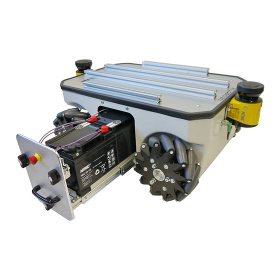
- Page 4 MPO-500 _ Download as PDF The mobile robot MPO-500 features four Mecanum wheels which provide an extraordinary manoeuvrability. Each Mecanum wheel has several independent rollers mounted along its circumference. The axles of the rollers are rotated at 45° to the wheel’s main axle. This design enables the robot to instantly move into any direction: The Mecanum wheels make it truly omnidirectional.
-
Page 5: Mpo-500
1.1 Product Information 1.1.1 Intended Use The MPO-500 has been designed for use in service robotics research. It can be used for a wide range of different experiments and tests in fields such as autonomous vehicles, mobile manipulation and factory automation. -
Page 6: Qualified Personnel
• Take care that no part of the cargo or additional components (e.g. cables, wires) can touch the wheels. • Make sure that the working space of the MPO-500 is free of all objects which might be caught in the wheels. -
Page 7: Operating Elements
Please contact Neobotix if the positions of the laser scanners has to be modified. 1.2 Operating Elements The figure below shows the tail of the MPO-500 and the most important operating elements. Fig. 1: Operating elements of the MPO-500 Emergency stop buttons... -
Page 8: Key Switch
CHAPTER 1. MPO-500 1.3. MECHANICAL PROPERTIES and turning the Key Switch (page 13) clockwise to position II for a few seconds. 1.2.2 Key Switch Key Switch (page 13). 1.2.3 Brake Release Button Pressing this button will open the motors’ brakes allowing the robot to be moved even while it is turned off. -
Page 9: Absolute Maximum Ratings
CHAPTER 1. MPO-500 1.3. MECHANICAL PROPERTIES Fig. 2: Dimensions of the MPO-500 1.3.2 Absolute Maximum Ratings Warning: Exceeding these ratings might cause malfunctions or damage the robot! Description Units Value Storage temperature °C -20 .. +50 Operating temperature (environmental temperature) °C... - Page 10 CHAPTER 1. MPO-500 1.3. MECHANICAL PROPERTIES Fig. 3: Coordinate system of MPO-500 Fig. 4: Positions of the laser scanners...
-
Page 11: Transport
1.4 Transport 1.4.1 Packaging The mobile robot MPO-500 is packed in a rugged wooden box which can be reused for future transports. If the original box cannot be used anymore it is recommended to build a new box of similar design. -
Page 12: Unpacking The Robot
1.4.3 Short Distance Transport For short distances the MPO-500 can also be transported in the trunk of a car without the wooden box. It still must be secured against sliding and should not be driven outdoors. -
Page 13: Cleaning
14. Align the top plate and arrange the foam rubber sealing properly to achieve best splash water protection. 15. Fasten the top plate to the platform and mount all modules removed earlier. If you encounter any problems, please contact Neobotix immediately. 1.5.4 Battery Replacement (Quick Change) The quick change system allows the batteries to be replaced without the use of tools. -
Page 14: Fuses
CHAPTER 1. MPO-500 1.6. TAKING OUT OF SERVICE 3. Unlock the battery drawer by turning the three black knobs counter-clockwise for 180°. 4. Slowly open the drawer. 5. Disconnect the batteries. 6. Lift the batteries out of the drawer. 7. Carefully place the replacement battery with the long cable into the drawer and push it fully inside. -
Page 15: Rohs Information
CHAPTER 1. MPO-500 1.7. LEGAL NOTES 1.7.2 RoHS Information As non-road mobile machinery our mobile robots are explicitly exempted from the scope of the RoHS directive 2011/65/EU. We have nevertheless followed the underlying principles of RoHS and tried to reduce the use of harmful... -
Page 16: General Hardware Information
General Hardware Information 2.1 Key Switch All Neobotix robots are equipped with a key switch to turn the robot on and off and to reset emergency stops. It can only be operated as long as the key is inserted. 2.1.1 Turning on To start the robot, turn the key clockwise (towards position II) until the LCD lights up and then release again. -
Page 17: Lc Display
MOTOR ERROR At least one motor is reporting an error. This state is quit automatically as soon as all motors are operational again. SAFETY RELAY FAIL One of the safety relays is damaged. Please contact Neobotix. POWER RELAY FAIL The power relays are damaged. Please contact Neobotix. -
Page 18: The Info View
CHAPTER 2. GENERAL HARDWARE INFORMATION 2.2. LC DISPLAY EMSTOP BUTTON FAIL One of the emergency stop buttons does not operate properly. Please contact Neobotix. CHARGE RELAY FAIL The charging relay is damaged. Please contact Neobotix. The charging contacts might still be connected to the batteries! CHECKSUM ERROR The protocol versions of the control software and the RelayBoard do not match. -
Page 19: Batteries
• Excess heat • Strong smell of sulphur • Liquid below the battery As soon as you notice any kind of damage the batteries must no longer be used and must not be charged any further! Please contact Neobotix immediately. -
Page 20: Charging
Warning: If you notice anything unusal about the LiFePO4 batteries immediately switch off the robot, stop charging and contact Neobotix! 2.3.2 Charging 2.3.2.1 With external Battery Charger The battery of the mobile robot consists of several batteries connected in series and / or in parallel. The resulting battery pack can be charged conveniently and safely by using the provided battery charger. -
Page 21: Recycling
Attention: Under European law all kinds of batteries must only be returned to certified recycling companies. Please get in touch with Neobotix if you are unsure about how to recycle or dispose of used batteries. 2.4 Charging Stations 2.4.1 Automatic Charging Station... - Page 22 The dimension of the charging station varies depending on the robot. The dimensions can be found in the table below: Robot MP-400 MP-500 MPO-700 MPO-500 2.4.1.2 After Installation After installing the charging station please check the height of the charging contacts and if the robot can reach the station without problems. Attention: Only plug in the power cable after successfully checking these two points.
-
Page 23: External Battery Charging Station
CHAPTER 2. GENERAL HARDWARE INFORMATION 2.4. CHARGING STATIONS 2.4.2 External Battery Charging Station If the robot is equipped with the battery quick change system the battery set that is currently not in use can be recharged in an external battery charging station. Place the charging station on the floor and make sure that it will not slip. - Page 24 CHAPTER 2. GENERAL HARDWARE INFORMATION 2.4. CHARGING STATIONS Fig. 2: Position of the main power switch (X)
-
Page 25: Connectors
Farnell RS Components AWG 28-24 182734-2 429715 532-456 In Neobotix products the pin assignment of the HE14 connectors is as shown below. 2.5.2 Würth Elektronik - MPC4 Please check the Würth Elektronik online catalogue for details on the MPC4 https://www.we-online.de/web/de/wuerth_elektronik/start.php... -
Page 26: Würth Elektronik - Mpc3
649010113322 649016113322 Crimp contacts Würth Elektronik AWG 24-18 64900613722 In Neobotix products the pin assignment of the MPC4 connectors is as shown below. 2.5.3 Würth Elektronik - MPC3 Please check the Würth Elektronik online catalogue for details on the MPC3 https://www.we-online.de/web/de/wuerth_elektronik/start.php... -
Page 27: Safety Instructions
Würth Elektronik AWG 24-20 66200113722 In Neobotix products the pin assignment of the MPC3 connectors is as shown below. 2.6 Safety Instructions 2.6.1 General Safety Instructions This page contains general safety instructions and information that applies to all Neobotix robots. -
Page 28: Briefing
2.6.1.1 Emissions All the components and sensors used in Neobotix robots are safe to use and do not emit any dangerous radiation. • The laser scanners are devices of laser safety class 1 or 1M. -
Page 29: Cooperating With The Robot
As long as the safety features of the mobile robot are set up properly, the presence of people and vehicles in the robot’s wider working area is allowed. Please contact Neobotix for further advice if needed. All people working in the same area as the robot should nevertheless be informed about the robot’s behaviour and the... -
Page 30: Bringing Into Service
Neobotix. Some detailed information or instruction might be necessary. In case one or more robots are to be modified, it is strongly recommended to consult Neobotix in order to provide the appropriate training and information for all technicians and programmers. The functions and safety of all modified robots have to be checked and ensured before bringing them into service. -
Page 31: Configuring The Safety Fields
The localisation system of the mobile robot requires clearly visible landmarks and a high quality map of the surround- ing. Further information on this topic can be found in the documentation of the used software. Please contact Neobotix in case of any problems. -
Page 32: Safety Instructions (Manipulators)
CHAPTER 2. GENERAL HARDWARE INFORMATION 2.7. SAFETY INSTRUCTIONS (MANIPULATORS) The configuration and diagnostics software CDS from Sick can be used to conveniently configure the scanners’ safety fields. The configuration cable that was included in delivery can be used to connect the scanners to the serial port of any external computer running the CDS. -
Page 33: Maintenance
CHAPTER 2. GENERAL HARDWARE INFORMATION 2.8. MAINTENANCE Note: Additional actions might be required to guarantee the appropriate level of safety! 2.8 Maintenance 2.8.1 Cleaning Before any cleaning starts the robot should be set into emergency stop by pressing one of the emergency stop buttons. It can also be switched off altogether. -
Page 34: Qualified Personnel
• A reduced uptime between charging cycles is often caused by old batteries that have lost a significant part of their capacity. 2.8.2.3 Repairs In case of any questions regarding repairs or replacement parts please get in touch with Neobotix. We are always happy to support you. Please mind the following points in any case: •... -
Page 35: Taking Out Of Service
CHAPTER 2. GENERAL HARDWARE INFORMATION 2.10. TAKING OUT OF SERVICE • all members of other departments of the company or institution in which the product is operated. This list is not intended to be exhaustive. 2.10 Taking out of Service 2.10.1 Disassembly Once the mobile robot has reached the end of its lifetime it should be disassembled and its components should be recycled. -
Page 36: Batteries
The Neobotix GmbH cannot be held responsible for any technical or typographical errors and reserves the right to make changes to the product and manual without prior notice. Neobotix makes no warranty of any kind with regard to the material contained within this document, including, but not limited to, the implied warranties of merchantability and fitness for a particular purpose.
Need help?
Do you have a question about the MPO-500 and is the answer not in the manual?
Questions and answers