Table of Contents
Advertisement
Quick Links
Advertisement
Table of Contents

Related Manuals for Gigabyte GA-F2A55-DS3


Summary of Contents for Gigabyte GA-F2A55-DS3
- Page 1 GA-F2A55-DS3 User's Manual Rev. 3001 12ME-F255DS3-3001R...
- Page 2 The trademarks mentioned in this manual are legally registered to their respective owners. Disclaimer Information in this manual is protected by copyright laws and is the property of GIGABYTE. No part of this manual may be reproduced, copied, translated, transmitted, or published in any form or by any means without GIGABYTE's prior written permission.
-
Page 3: Table Of Contents
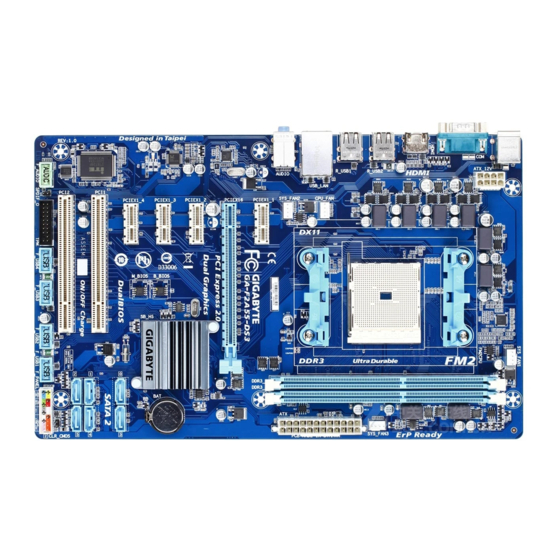
Table of Contents GA-F2A55-DS3 Motherboard Layout ................4 GA-F2A55-DS3 Motherboard Block Diagram ..............5 Chapter 1 Hardware Installation ..................6 Installation Precautions ..................6 ..................7 Installing the APU ..................... 9 Installing the Memory ..................9 Installing an Expansion Card ................. 10 ..........10 Back Panel Connectors .................. -
Page 4: Ga-F2A55-Ds3 Motherboard Layout
GA-F2A55-DS3 Motherboard Layout KB_MS CPU_FAN ATX_12V Socket FM2+ HDMI R_USB2 R_USB1 SYS_FAN1 USB_LAN SYS_FAN2 AUDIO PCIEX1_1 GA-F2A55-DS3 Realtek ® PCIEX16 GbE LAN PCIEX1_2 CODEC AMD A55 PCIEX1_3 B_BIOS PCIEX1_4 M_BIOS PCI1 PCI2 CLR_CMOS F_AUDIO SPDIF_O F_USB3 F_USB2 F_USB1 F_PANEL F_USB4... -
Page 5: Ga-F2A55-Ds3 Motherboard Block Diagram
GA-F2A55-DS3 Motherboard Block Diagram 1 PCI Express x16 1 PCI Express x1 PCIe CLK AMD APU Dual Channel Memory HDMI PCI Express Bus 3 PCI Express x1 Dual BIOS RJ45 Realtek ® PCIe CLK 6 SATA 3Gb/s GbE LAN 14 USB 2.0/1.1... -
Page 6: Chapter 1 Hardware Installation
Chapter 1 Hardware Installation Installation Precautions The motherboard contains numerous delicate electronic circuits and components which can become manual and follow these procedures: Prior to installation, make sure the chassis is suitable for the motherboard. warranty sticker provided by your dealer. These stickers are required for warranty validation. Always remove the AC power by unplugging the power cord from the power outlet before installing or removing the motherboard or other hardware components. - Page 7 FM2+ Socket: AMD A series processors AMD Athlon ™ series processors Chipset AMD A55 Memory 2 x 1.5V DDR3 DIMM sockets supporting up to 64 GB of system memory * Due to a Windows 32-bit operating system limitation, when more than 4 GB of physical the physical memory installed.
- Page 8 ® Software Operating Support for Windows 8.1/8/7 32-bit/64-bit * If you plan to install Windows 8.1, please download the latest drivers from GIGABYTE's System website. Support for Windows Vista/XP 32-bit * To support Windows Vista/XP 32-bit, you must install an AMD FM2 Trinity APU.
-
Page 9: Installing The Apu
Form Factor ATX Form Factor; 30.5cm x 19.0cm prior notice. * Please visit the Support & Downloads\Utility for the software listed in the "Unique Features" and "Bundled Software" columns. Installing the APU Read the following guidelines before you begin to install the APU: Make sure that the motherboard supports the APU. -
Page 10: Installing An Expansion Card
This motherboard provides two DDR3 memory sockets and supports Dual Channel Technology. After the memory Channel memory mode will double the original memory bandwidth. The two DDR3 memory sockets are divided into two channels and each channel has one memory socket as following: Channel A: DDR3_2 Channel B: DDR3_1... -
Page 11: Back Panel Connectors
Back Panel Connectors PS/2 Keyboard and PS/2 Mouse Port Serial Port Use the serial port to connect devices such as a mouse, modem or other peripherals. HDMI Port The HDMI port is HDCP compliant and supports Dolby True HD and DTS HD output. - Page 12 Line In Jack (Blue) Mic In Jack (Pink) multi-channel audio feature through the audio driver. device and then remove it from the motherboard. When removing the cable, pull it straight out from the connector. Do not rock it side to side to prevent an electrical short inside the cable connector.
-
Page 13: Internal Connectors
Internal Connectors ATX_12V F_USB1/F_USB2/F_USB3/F_USB4 SATA2 0/1/2/3/4/5 Read the following guidelines before connecting external devices: First make sure your devices are compliant with the connectors you wish to connect. Before installing the devices, be sure to turn off the devices and your computer. Unplug the power cord from the power outlet to prevent damage to the devices. - Page 14 1/2) ATX_12V/ATX (2x4 12V Power Connector and 2x12 Main Power Connector) With the use of the power connector, the power supply can supply enough stable power to all the components off and all devices are properly installed. The power connector possesses a foolproof design. Connect the power supply cable to the power connector in the correct orientation.
- Page 15 SYS_FAN3 Pin No. +12V SYS_FAN3 Be sure to connect fan cables to the fan headers to prevent your APU and system from overheating. Overheating may result in damage to the APU or the system may hang. Open: Normal Short: Clear CMOS Values Always turn off your computer before clearing the CMOS values.
- Page 16 7) BAT (Battery) in the CMOS when the computer is turned off. Replace the battery when the battery voltage drops to a low level, or the CMOS values may not be accurate or may be lost. You may clear the CMOS values by removing the battery: 1.
- Page 17 your chassis front panel audio module to this header. Make sure the wire assignments of the module connector match the pin assignments of the motherboard header. Incorrect connection between the module connector and the motherboard header will make the device unable to work or even damage it. For HD Front Panel Audio: For AC'97 Front Panel Audio: Pin No.
-
Page 18: Chapter 2 Bios Setup
To access the BIOS Setup program, press the <Delete> key during the POST when the power is turned on. To upgrade the BIOS, use either the GIGABYTE Q-Flash or @BIOS utility. Q-Flash allows the user to quickly and easily upgrade or back up BIOS without entering the operating system. -
Page 19: Startup Screen
Startup Screen The following startup Logo screen will appear when the computer boots. Function Keys On the main menu of the BIOS Setup program, press arrow keys to move among the items and press <Enter> to accept or enter a sub-menu. Or you can use your mouse to select the item you want. M.I.T. - Page 20 M.I.T. Current Status This screen provides information on CPU/memory frequencies/parameters. Advanced Frequency Settings BCLK/PCIe Clock Control Important: It is highly recommended that the CPU frequency be set in accordance with the CPU Processor Graphics Clock CPU Clock Ratio being installed. CPU Frequency Displays the current operating CPU frequency.
- Page 21 enabled. System Memory Multiplier Allows you to set the system memory multiplier. Auto sets memory multiplier according to memory SPD Memory Frequency (MHz) BCLK/PCIe Clock Control and System Memory Multiplier settings. Advanced Memory Settings , System Memory Multiplier, Memory Frequency(MHz) The settings above are synchronous to those under the same items on the Advanced Frequency Settings menu.
- Page 22 Channel A/B Timing Settings This sub-menu provides memory timing settings for each channel of memory. The respective timing setting DRAM Timing Selectable is set to Quick or Expert. Note: Your system may become unstable or fail to boot after you make changes on the memory timings. If this occurs, please reset Advanced Voltage Settings This sub-menu allows you to set CPU, chipset and memory voltages.
-
Page 23: System Information
Silent Allows the fan to run at slow speeds. Manual Allows you to control the fan speed under the Slope PWM item. Disabled Allows the fan to run at full speeds. Slope PWM 1st System Fan Speed Control is set to Manual. Options are: 0.75 PWM value / Silent Allows the fan to run at slow speeds. -
Page 24: Bios Features
System Date value. System Time Sets the system time. The time format is hour, minute, and second. For example, 1 p.m. is 13:0:0. Use key to set the desired value. Access Level BIOS settings; the User level only allows you to make changes to certain BIOS settings but not all. Hard Drive BBS Priorities submenu will be presented here. - Page 25 A password is only required for entering the BIOS Setup program. System A password is required for booting the system and for entering the BIOS Setup program. Allows you to determine whether to display the GIGABYTE Logo at system startup. Disabled skips the CSM Support Never Disables UEFI CSM and supports UEFI BIOS boot process only.
-
Page 26: Peripherals
Administrator Password BIOS Setup. Differing from the user password, the administrator password allows you to make changes to all BIOS settings. User Password Setup. However, the user password only allows you to make changes to certain BIOS settings but not all. To cancel the password, press <Enter>... - Page 27 HD Audio Azalia Device If you wish to install a 3rd party add-in audio card instead of using the onboard audio, set this item to Disabled. If you wish to install a 3rd party add-in network card instead of using the onboard LAN, set this item to Disabled.
-
Page 28: Power Management
ATA Port Information This section provides information on the device connected to each SATA port controlled by AMD Chipset. Serial Port A Power Management Resume by Alarm If enabled, set the date and time as following: Wake up hour/minute/second: Set the time at which the system will be powered on automatically. Note: When using this function, avoid inadequate shutdown from the operating system or removal of the AC power, or the settings may not be effective. - Page 29 Delay 4 Sec. Press and hold the power button for 4 seconds to turn off the system. If the power button is pressed for less than 4 seconds, the system will enter suspend mode. AC BACK Determines the state of the system after the return of power from an AC power loss. Memory The system returns to its last known awake state upon the return of the AC power.
-
Page 30: Save & Exit
Save & Exit Save & Exit Setup Press <Enter> on this item and select Yes. This saves the changes to the CMOS and exits the BIOS Setup program. Select or press <Esc> to return to the BIOS Setup Main Menu. Exit Without Saving Press <Enter>... -
Page 31: Chapter 3 Appendix
Chapter 3 Appendix Before you begin Motherboard driver disk. A. Installing SATA hard drive(s) in your computer Attach one end of the SATA signal cable to the rear of the SATA hard drive and the other end to available SATA port on the motherboard. - Page 32 Step 3: The Main Menu to select Logical Drive Main Menu and press <Enter>. Step 4: To create an array, press <Enter> on Logical Drive Create Menu. Step 5: Usable hard drives are listed on the Logical Drive Create Menu. Use the up or down arrow key to select the hard drive to be included in the array and press the <Space>...
-
Page 33: Drivers Installation
Making a SATA RAID/AHCI Driver Diskette \BootDrv\Hxp folder in the motherboard driver disk the OS installation. To copy the RAID/AHCI driver for Windows 8, copy the whole Hw8_A85 folder under the BootDrv A. Installing Windows XP Restart your system to boot from the Windows XP setup disk and press <F6> as soon as you see the message RAID/AHCI driver. - Page 34 - 34 -...
-
Page 35: Regulatory Statements
This document must not be copied without our written permission, and the contents there of must not be imparted Contravention will be prosecuted. We believe that the information contained herein was accurate in all respects at the time of printing. GIGABYTE cannot, however, assume any responsibility for errors or omissions in this text. as a commitment by GIGABYTE. -
Page 36: Contact Us
Address: No.6, Bao Chiang Road, Hsin-Tien Dist., New Taipei City 231,Taiwan TEL: +886-2-8912-4000, FAX: +886-2-8912-4005 You may go to the GIGABYTE website, select your language in the language list on the top right corner of the website. GIGABYTE Global Service System question, please link to: http://ggts.gigabyte.com.tw...
Need help?
Do you have a question about the GA-F2A55-DS3 and is the answer not in the manual?
Questions and answers