Advertisement
Quick Links
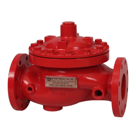
DELUGE VALVE
MODEL-H3
TECHNICAL DATA
MODEL
NOMINAL SIZE
SERVICE PRESSURE
END CONNECTION
THREADED OPENING BSPT
MOUNTING
FACTORY
HYDROSTATIC
TEST PRESSURE
FLANGE
CONNECTION
WET PILOT
SPRINKLER
HEIGHT LIMITATION
NET WEIGHT
WITHOUT TRIM
FINISH
APPROVAL
ORDERING
INFORMATION
GROOVE PIPE SIZE:
NOMINAL SIZE
2" (50 NB)
3" (80 NB)
4" (100 NB)
6" (150 NB)
6" (150 NB)
8" (200 NB)
NOTE: FOR 6"(150 NB) STANDARD SUPPLY IS 168.3 mm OD
GROOVE PIPE.
FOR 165.1mm REQUIREMENT, SPECIFY IN ORDER
MARCH, 2022
(DUCTILE IRON)
H3-Ductile Iron ASTM A
536-77 GRADE 65-45-12
200, 150, 100, 80 & 50NB
1.4 to 17.6 kg/sq.cm
(20 to 250 psi)
Flange X Flange
Groove X Groove
Vertical or Horizontal
35 kg/sq.cm (500 psi)
ANSI B 16.5 #150 FF
is standard supply.
(Contact HD Sales for other
options)
As per graph in the
catalogue
FXF
200 NB - 153 kg
143 kg
150 NB -
79 kg
100 NB -
50 kg
80 NB -
35 kg
50 NB -
32 kg
Red to RAL 3001
UL Listed
1. Size of valve
2. Flange specification or for
Grooved end specify pipe
outside diameter
3. Valve mounting- Horizontal
or Vertical
4. Trim type
Pipe OD in mm
60.3
89.0
114.3
165.1
168.3
219.1
GXG
68 kg
DESCRIPTION
42 kg
29 kg
Deluge Valve is known as a system control valve in
27 kg
a deluge system, used for fast application of water
in a spray system. Deluge valve protects areas such
as power transformer installation, storage tank,
conveyor protection and other industrial application
etc. With the addition of foaming agent, deluge valve
can be used to protect aircraft hanger and inflammable
liquid fire.
VALVE OPERATION
HD Deluge Valve is a quick release, hydraulically
operated diaphragm valve. It has three chambers,
isolated from each other by the diaphragm operated
clapper and seat seal. While in SET position, water
pressure is transmitted through an external bypass
check valve and restriction orifice from the system
supply side to the top chamber,
pressure in the top chamber act across the diaphragm
operated clapper which holds the seat against the
inlet supply pressure, because of the differential
pressure design. On detection of fire, the top chamber
is vented to atmosphere through the outlet port via
opened actuation devices. The top chamber pressure
cannot be replenished through the restricted inlet
port, and the upward force of the supply pressure
lifts the clapper allowing the water flow to the system
piping network and alarm devices.
PAGE 1 OF 16
HD FIRE PROTECT
PVT. LTD.
so that supply
HD 235
Advertisement

Summary of Contents for HD FIRE PROTECT H3
- Page 1 DELUGE VALVE MODEL-H3 HD FIRE PROTECT (DUCTILE IRON) PVT. LTD. TECHNICAL DATA MODEL H3-Ductile Iron ASTM A 536-77 GRADE 65-45-12 NOMINAL SIZE 200, 150, 100, 80 & 50NB SERVICE PRESSURE 1.4 to 17.6 kg/sq.cm (20 to 250 psi) END CONNECTION...
- Page 2 HD FIRE PROTECT PVT. LTD. TRIM DESCRIPTION b) WET PILOT TRIM (HYDRAULIC RELEASE) Wet pilot operation uses a pilot line of closed The trims are functionally termed as Dry Pilot Trim, Sprinklers/QB Detectors containing pressurized Wet Pilot Trim, Electric Trim and Test & Alarm Trim as water, supplied through the upstream side of per the method of actuation of the deluge valve.
-
Page 3: Resetting Procedure
HD FIRE PROTECT PVT. LTD. TRIM TYPES B. When priming connection is from the inlet of Deluge Valve (Auto resetting) The trims are designated as following: (i) The deluge valve will reset automatically when W =Wet Pilot trim D = Dry Pilot Trim... -
Page 4: Inspection And Maintenance
HD FIRE PROTECT PVT. LTD. INSPECTION AND MAINTENANCE (iv) PERIODIC CHECK Conduct the water flow test by actuating few of Installed system piping network must be flushed the release devices provided in the system. Clean properly before placing the Deluge valve in service. - Page 5 HD FIRE PROTECT PVT. LTD. DELUGE VALVE MODEL - H3 SIZE 200 / 150 / 100 / 80/ 50 NB Groove x Groove Flange x Flange MARCH, 2022 PAGE 5 OF 16 HD 235...
-
Page 6: Material Specification
HD FIRE PROTECT PVT. LTD. DELUGE VALVE MODEL - H3 SIZE 200 / 150 / 100 / 80 / 50 NB DIMENSION in millimeter (Approximate) VALVE NOMINAL SIZE F x F G x G 200 NB 150 NB 100 NB... - Page 7 HD FIRE PROTECT PVT. LTD. SCHEMATIC FOR BASIC WET PILOT TRIM FOR DELUGE VALVE MODEL - H3 FOR VERTICAL MOUNTING ET-W TO DETECTION LINE TO DETECTION LINE FLANGE X FLANGE GROOVE X GROOVE SCHEMATIC 1 SCHEMATIC FOR BASIC DRY PILOT TRIM FOR DELUGE VALVE...
- Page 8 HD FIRE PROTECT PVT. LTD. SCHEMATIC FOR BASIC WET PILOT TRIM FOR DELUGE VALVE MODEL - H3 FOR VERTICAL MOUNTING ETW-T TO DETECTION LINE TO DETECTION LINE GROOVE X GROOVE FLANGE X FLANGE SCHEMATIC 3 SCHEMATIC FOR BASIC DRY PILOT TRIM FOR DELUGE VALVE...
- Page 9 HD FIRE PROTECT PVT. LTD. SCHEMATIC FOR BASIC WET PILOT TRIM FOR DELUGE VALVE MODEL - H3 FOR VERTICAL MOUNTING ETW-D DR.V DR.V TO DETECTION LINE TO DETECTION LINE FLANGE X FLANGE GROOVE X GROOVE SCHEMATIC 5 SCHEMATIC FOR BASIC DRY PILOT TRIM FOR DELUGE VALVE...
- Page 10 HD FIRE PROTECT PVT. LTD. SCHEMATIC FOR BASIC WET PILOT TRIM FOR DELUGE VALVE MODEL - H3 FOR VERTICAL MOUNTING NT-W DR.V DR.V TO DETECTION LINE TO DETECTION LINE FLANGE X FLANGE GROOVE X GROOVE SCHEMATIC 7 SCHEMATIC FOR BASIC DRY PILOT TRIM FOR DELUGE VALVE...
- Page 11 HD FIRE PROTECT PVT. LTD. SCHEMATIC FOR BASIC WET PILOT TRIM FOR DELUGE VALVE MODEL - H3 FOR HORIZONTAL MOUNTING ET-W TO DETECTION TO DETECTION LINE LINE OUTLET OUTLET INLET INLET GROOVE X GROOVE FLANGE X FLANGE SCHEMATIC 9 SCHEMATIC FOR BASIC DRY PILOT TRIM FOR DELUGE VALVE...
- Page 12 HD FIRE PROTECT PVT. LTD. SCHEMATIC FOR BASIC WET PILOT TRIM FOR DELUGE VALVE MODEL - H3 FOR HORIZONTAL MOUNTING ETW-T TO DETECTION TO DETECTION LINE LINE OUTLET OUTLET INLET INLET GROOVE X GROOVE FLANGE X FLANGE SCHEMATIC 11 SCHEMATIC FOR BASIC DRY PILOT TRIM FOR DELUGE VALVE...
- Page 13 HD FIRE PROTECT PVT. LTD. SCHEMATIC FOR BASIC WET PILOT TRIM FOR DELUGE VALVE MODEL - H3 FOR HORIZONTAL MOUNTING TO DETECTION TO DETECTION ETW-D LINE LINE OUTLET OUTLET INLET INLET DR.V DR.V FLANGE X FLANGE GROOVE X GROOVE SCHEMATIC 11...
- Page 14 HD FIRE PROTECT PVT. LTD. SCHEMATIC FOR BASIC WET PILOT TRIM FOR DELUGE VALVE MODEL - H3 FOR HORIZONTAL MOUNTING NT-W TO DETECTION TO DETECTION LINE LINE OUTLET OUTLET INLET INLET DR.V DR.V GROOVE X GROOVE FLANGE X FLANGE SCHEMATIC 15...
- Page 15 HD FIRE PROTECT PVT. LTD. SPRINKLER HEIGHT LIMITATION DV 200NB DV 150NB KG/SQ.CM KG/SQ.CM 220. 220. 40 40 40 40 SYSTEM SUPPLY PRESSURE - PSI ------ SYSTEM SUPPLY PRESSURE - PSI ------ EQUIVALENT LENGTH BASED ON 1/2” SCHEDULE 40 PIPE WITH C=120 EQUIVALENT LENGTH BASED ON 1/2”...
- Page 16 LIMITED WARRANTY HD FIRE PROTECT PVT. LTD. hereby referred to as HD FIRE warrants to the original purchaser of the fire protection products manufactured by HD FIRE and to any other person to whom such equipment is transferred, that such products will be free from defect in material and workmanship under normal use and care, for two (2) years from the date of shipment by HD FIRE.
Need help?
Do you have a question about the H3 and is the answer not in the manual?
Questions and answers