Table of Contents
Advertisement
Quick Links
Small Cell Radio Node - SCRN-530 Hardware Installation
Guide
DOC-SCRN-530-HIG
Issue 1
Related Literature | Search www.Corning.com/opcomm. Click Required Resources.
Table 1
Revision History
Issue
Date
Summary of Changes
1
21JUL21
First issue for SCRN-530 Small Cell Radio Node.
SCRN-530 Hardware Installation Guide | DOC-SCRN-530-HIG | 21 July, 2021 | Page 1
Advertisement
Table of Contents

Summary of Contents for CORNING SCRN-530
- Page 1 Issue 1 Related Literature | Search www.Corning.com/opcomm. Click Required Resources. Table 1 Revision History Issue Date Summary of Changes 21JUL21 First issue for SCRN-530 Small Cell Radio Node. SCRN-530 Hardware Installation Guide | DOC-SCRN-530-HIG | 21 July, 2021 | Page 1...
-
Page 2: Table Of Contents
Section 10. Completing the Installation ........... . . 16 Section 11. Detaching the SCRN-530 from the Mounting Brackets ......16 Section 12. -
Page 3: Fcc Statements
• Wall installation should be avoided, if a minimum safety distance of 40 cm cannot be maintained. WARNING: All electrical equipment must be properly grounded. Refer to national and local electrical codes and any other relevant standards for electrical grounding information. SCRN-530 Hardware Installation Guide | DOC-SCRN-530-HIG | 21 July, 2021 | Page 3... -
Page 4: Other Cautions
CAUTION: ESD can damage the SCRN-530 and internal components. Ensure that the SCRN-530 and associated antenna equipment is installed and serviced according to national and local ESD standards. CAUTION: Do not open the SCRN-530 casing. E-RAN wireless system equipment must only be serviced by Corning-accredited personnel. Opening the SCRN-530 casing voids the warranty. -
Page 5: Section 1. System Overview
LED behavior both during the boot-up and under normal operating conditions. NOTE: The SCRN-530 small cell radio node is referred to as “radio node” in the rest of this document. -
Page 6: Section 3. Radio Node Model
SCRN-530 model configuration. Table 1 Radio Node Configuration Radio Node Model Description Antenna Type SCRN-530-39 39 GHz band n260 mmWave RN with 8 x 8 Internal dual-polarization antenna array SCRN-530 Hardware Installation Guide | DOC-SCRN-530-HIG | 21 July, 2021 | Page 6... -
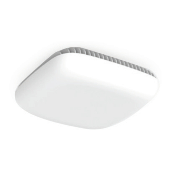
Page 7: Section 4. Scrn-530 Views
4. SCRN-530 Views Figure 2 Figure 3 display views of the SCRN-530. Figure 2 SCRN-530 Cover Figure 3 SCRN-530 With Ceiling-Mount Bracket SCRN-530 Hardware Installation Guide | DOC-SCRN-530-HIG | 21 July, 2021 | Page 7... -
Page 8: Section 5. Connectors, Sfp+ And Micro-Usb Ports, And Status Led
SCRN-530 Connectors and Status LED Phoenix Power Cable Port The SCRN-530 has a 48 VDC power connector for delivering power from a Corning PSU6 DC Power Supply Unit or equivalent to the radio node. Plug the Phoenix power connector from the power source cable into the power connector. -
Page 9: Section 6. System Specifications
IEEE 1588v2-based (PTP) synchronization with an external PTP grandmaster clock Mounting Wall or Ceiling, brackets included Brackets support four wall-mount tilting options: 0°, 15°, 30°, and 45° tilt Cooling Method Passive convection cooling SCRN-530 Hardware Installation Guide | DOC-SCRN-530-HIG | 21 July, 2021 | Page 9... -
Page 10: Section 7. Compliance
Table 3 Radio Node Compliance Safety Safety: UL-62368-1 2nd Edition FCC Compliant: Part 15 (Class A), Part 30 FCC 47 CFR 1.1307(b) MPE: FCC 47 CFR 1.1310 SCRN-530 Hardware Installation Guide | DOC-SCRN-530-HIG | 21 July, 2021 | Page 10... -
Page 11: Section 8. Mounting The Scrn-530
8. Mounting the SCRN-530 The SCRN-530 can be installed on walls and below ceilings with the factory-provided brackets. When mounting a radio node on a wall, position the cooling fins vertically. The factory-provided wall-mount bracket can tilt the radio node down at the following angles: 0°, 15°, 30°... - Page 12 T-bar ceiling. Step 4 Secure the ceiling-mount bracket to ceiling tethering system. Step 5 Slide the radio node back onto the bracket and gently tighten the securing screw. SCRN-530 Hardware Installation Guide | DOC-SCRN-530-HIG | 21 July, 2021 | Page 12...
-
Page 13: Installing The Scrn-530 On A Wall
Radio Node Wall-Mount Bracket When using the multi-angle wall-mount bracket, it is not necessary to remove the ceiling-mount bracket from the radio node; the wall-mount bracket attaches to the SCRN-530 Hardware Installation Guide | DOC-SCRN-530-HIG | 21 July, 2021 | Page 13... - Page 14 - Then, set the radio node to the required tilt, and tighten the wall- mount bracket captive securing screw to lock the radio node tilt angle. SCRN-530 Hardware Installation Guide | DOC-SCRN-530-HIG | 21 July, 2021 | Page 14...
-
Page 15: Section 9. Cabling Guidelines
• Make sure that the radio node is fully secured to the mounting brackets so that it locks into place. A correctly-installed cable should at no time during installation impede inserting the radio node into the mounting brackets. SCRN-530 Hardware Installation Guide | DOC-SCRN-530-HIG | 21 July, 2021 | Page 15... -
Page 16: Section 10. Completing The Installation
On failure, the LED state display the state that encountered the failure. Table 4 shows the SCRN-530 boot sequence and corresponding LED behavior. SCRN-530 Hardware Installation Guide | DOC-SCRN-530-HIG | 21 July, 2021 | Page 16... - Page 17 The radio node moves to the unit for routing issues. next state (State 4) upon getting a JOIN GRANT from the centralized unit. SCRN-530 Hardware Installation Guide | DOC-SCRN-530-HIG | 21 July, 2021 | Page 17...
-
Page 18: Section 13. Scrn-530 Led Management
• while the radio node is booting • if the radio node or cell is in fault state Table 5 lists the default LED behavior of the radio node. SCRN-530 Hardware Installation Guide | DOC-SCRN-530-HIG | 21 July, 2021 | Page 18... -
Page 19: Section 14. Disabling The Led Display
DefaultMode Standard %set System RadioNode LED DefaultMode Standard Step 2 Issue the command to verify the show System RadioNode LED configuration: %show System RadioNode LED DefaultMode Standard; SCRN-530 Hardware Installation Guide | DOC-SCRN-530-HIG | 21 July, 2021 | Page 19... -
Page 20: Section 16. Sfp+ Led Indications
800-743-2675 • FAX: 828-325-5060 • International: +1-828-901-5000 • www.corning.com/opcomm Corning Optical Communications reserves the right to improve, enhance, and modify the features and specifications of Corning Optical Communications products without prior notification. A complete listing of the trademarks of Corning Optical Communications is available at www.corning.com/opcomm/trademarks. All other trademarks are the properties of their respective owners.
Need help?
Do you have a question about the SCRN-530 and is the answer not in the manual?
Questions and answers