
Summary of Contents for Fuling Inverter DZB100 Series
- Page 1 220Vseries 220Vseries: 0.5~3.7KW 0.5~3.7KW 400Vseries: 0.5~400KW 400Vseries: 0.5~400KW 660Vseries: 15~630KW 660Vseries: 15~630KW 1140Vseries: 55~630KW 1140Vseries: 55~630KW...
- Page 2 ABLE ABLE OF CONTENT CONTENTS Preface Preface Chapter 1 Introduction Chapter 1 Introduction Chapter 2 Installation and Wiring Chapter 2 Installation and Wiring Chapter 3 Digital Keypad Operation Chapter 3 Digital Keypad Operation Chapter 4 Start Up Chapter 4 Start Up Chapter 5 Summary of Parameter Settings Chapter 5 Summary of Parameter Settings Chapter 6 Parameter Settings...
- Page 3 ABLE ABLE OF CONTENT CONTENTS Preface Preface Chapter 1 Introduction Chapter 1 Introduction Chapter 2 Installation and Wiring Chapter 2 Installation and Wiring Chapter 3 Digital Keypad Operation Chapter 3 Digital Keypad Operation Chapter 4 Start Up Chapter 4 Start Up Chapter 5 Summary of Parameter Settings Chapter 5 Summary of Parameter Settings Chapter 6 Parameter Settings...
- Page 4 This manual is This manual is for DZB100 Series for DZB100 Series AC Motor AC Motor Drive.
- Page 5 DZB1 DZB100 Seri Series In In Chapter 1 Introduction Chapter 1 Introduction ur p po s hi s ha p pt e ro v vi d pe c ci f fi c im p pl e nf o or m ma t ti o unpack install...
- Page 6 DZB100 Series In tr od uc ti on 1.2 Nameplate Information Example: MODEL:DZB100B0075L4A INPUT: 3PH 380V 50/60Hz OUTPUT: 3PH 0~380V 0~400Hz POWER: 7.5KW 18.0A S / N : F L 7 5 / 0 5 0 5 8 8 8 8 TAIZHOU FULING ELECTROMOTOR CO.,L TD.
- Page 7 DZB100 Series In tr od uc ti on Description of Serial Name: Series Code E x pl a na ti o n Applicable Motor High-Perfo rmance General-Purpose AC Motor Drives B Series 0.55~400KW P Series Specific AC Motor Drives For Fan&Pump 7.5~400KW...
- Page 8 DZB100 Series In st al la ti on an d Wi ri ng Chapter 2 Installation and Wiring C ha pt er 2 p ro vi de s t he i nf or ma ti on n ee de d t o p ro pe rl y...
- Page 9 DZB100 Series In st al la ti on an d Wi ri ng 2.2 Wiring Main Circuit Wiring (1) Power terminal block designations Power input and output may be connected via a nine or ten position termina block. The pin assignments are as follows: Applicable motor ...
- Page 10 DZB100 Series In st al la ti on an d Wi ri ng (2) Power block terminal designations Description Terminals T ( L AC input line terminals Motor connection B R +( D C+ ) B R - Connection for the regenerative resistor (option)
- Page 11 DZB100 Series In st al la ti on an d Wi ri ng 8.To reverse the direction of rota tion, interchange any two connections of the three mot or leads. 9.The control lines and power line s (R,S,T;U,V,W;P,N,BR+,BR-) should be separated a nd avoid pa ra ll el wi ri ng le st it sh ou ld ge ne ra te no is e an d ca use mi s- op er at io n.
- Page 12 DZB100 Series In st al la ti on an d Wi ri ng Control Circuit Wiring (1) Control terminal block designations The control leads must be routed separately from the power supply and motor leads. They must not be fed through the same cable conduit.
- Page 13 DZB100 Series In st al la ti on an d Wi ri ng 2.3 Basic Wiring Diagram Users must connect wires according to the fo llowing circuit diagram shown below. Do not plug a Modem or telephone line to the RS-485 communication port, permanent damage may result.
- Page 14 DZB100 Series In st al la ti on an d Wi ri ng Braking unit (option) Use a disconnect Braking resistior and fuse R Power source 3 phase DCLinkReactor(option) 200-240V or 380-480V 50/60Hz W DC 20V ~ 24V ( 50mA Max. ) E ...
- Page 15 DZB100 Series In st al la ti on an d Wi ri ng Use a disconnect and fuse Power source R 3 phase 200-240V or 380-480V 50/60Hz W DC 20V ~ 24V ( 50mA Max. ) E Grounding Multi-function input 1...
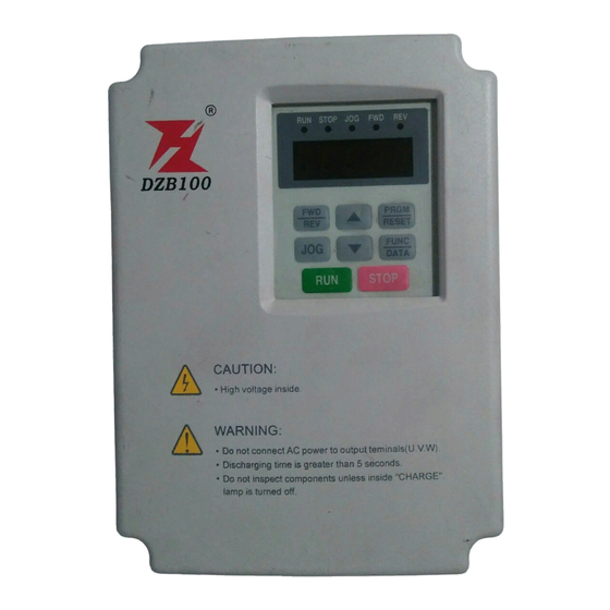
- Page 16 DZB100 Series Di gi ta l K ey pa d O pe ra ti on Chapter 3 Digital Keypad Operation Chapter 3 describes the various controls and indicators found on the digital keypad of the DZB100 AC drive. The information in this chapter should be read and understood before performing the start-up procedures described in Chapter 4.
- Page 17 DZB100 Series Di gi ta l K ey pa d O pe ra ti on Description Program / Reset Used to select the Normal mode of operation or to program the AC drive when PRGM either the drive is running or h as stopped. Switch to the PRGM mode to select RESET a parameter or change the setting of a parameter.
- Page 18 DZB100 Series Di gi ta l K ey pa d O pe ra ti on 3.2 Explanation of Screen Display Explanation of Displayed Messages Description Displayed Message Displays the AC drive output frequency controlled by the Maximum Output Frequency (F1- 03), Jog Frequenc y (F1- 16), or by the Multi-Function Input Terminals (F1-39-41).
- Page 19 DZB100 Series Di gi ta l K ey pa d O pe ra ti on Explanation of the LED Indicators RUN STOP JOG Red lamp lights during REV operation. Red lamp lights during FWD operation. Red lamp lights during JOG.
- Page 20 DZB100 Series Di gi ta l K ey pa d O pe ra ti on 3.3 Digital Keypad Operating Modes & Programming steps Pressing the key after power on will cause the AC drive to operate at 60 Hz, which is the factory default setting.
Need help?
Do you have a question about the DZB100 Series and is the answer not in the manual?
Questions and answers