Table of Contents
Advertisement
Quick Links
Advertisement
Table of Contents

Subscribe to Our Youtube Channel
Summary of Contents for Rish PFC 08L
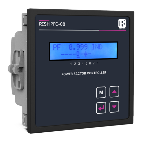
- Page 1 Power Factor Controller RISH PFC 08L Operation Manual REV-A 05/2019...
-
Page 2: Table Of Contents
Installation & Operating Instructions Section Contents Introduction Measurement Reading Screen Set Up Screens Installation EMC Installation Requirements Case Dimension and Panel Cutout Wiring Auxiliary Supply Fusing Earth/Ground Connections Connection Diagram Specifications REV-A 05/2019... -
Page 3: Introduction
1. Introduction The Power Factor Controller is a modern control device of innovative design with x1000 auto bank detection function. LEAD It is designed for a measuring voltage of 80 to 300 Vac. Display of Power Factor with Auto Detection Function makes ease of operation. - Page 4 Parameter Name x1000 Multiplier Indication Parameter Value x1000 x1000 Lag Indication LEAD LEAD Lead Indication Up Key Down Key Display is ultra bright 3 Digit LED display with power factor value with lead and Lag indication.
-
Page 5: Measurement Reading Screen
2 . Measurement Reading Screen "PF" on the screen indicates Power Factor parameter. x1000 "0.98" inductive on the screen LEAD indicates Power Factor value. Lag LED glows when power factor is inductive. Lead LED glows when power factor is capacitive. Lead / Lag LED is also used for target power factor programming x1000 LED glow when CT primary... - Page 6 ......n=number of (Manual relay on/off) ..banks available (Quit from Setup)
-
Page 7: Set Up Screens
3. Setup Screen Upon pressing both Up and Down keys simultaneously for 3 sec "Cod" screen is displayed. Entering of correct code scrolls all programmable parameters. Key function which common to all parameters are explained below Editing of digits ( Setting value ) Upon display of setup parameter label pressing key enter into setup and present value is shown. - Page 8 3.1 Target power factor Setting The Screen followed by label tPF is target power factor setting. x1000 once required PF value to set then LEAD LAG or LEAD PF can be set on LEDs' Range for power factor is 0.8 Lead to 0.8 Lag.
- Page 9 Undercurrent fault value are set with respect to CT primary. The value of 1 kA is as shown in the x1000 screen LEAD if valid value set then, pressing to move forward for CT Secondary Setting. 3.3 CT Secondary Setting The Screen shown further is used to set CT secondary.
- Page 10 3.4 Capacitor Bank Selection Mode: The Screen displays "Mod" followed by Its mode "Ato" or "CtL" . Pressing the will enter to edit capacitor x1000 bank selection mode. LEAD Pressing will scroll between "Ato" and "Ctl" mode. to set value press key.
- Page 11 At start of Auto Initialization display shows "Ato" 1. Auto Init enables detection of phase correction angle between voltage and current , number of capacitor bank and capacitor bank kVAr connected. Auto option will become "No" automatically once auto initialization is completed successfully.
- Page 12 3.6 Control Series Setting: This Setting is for selecting capacitor bank values in control series mode The Screen displays "CtL" followed by x1000 previously set Control Series Value. LEAD Pressing the will enter to edit value of control Series. The range of control series setting is "1 to 9" and "u".
- Page 13 The Control Series Selection will act as an Multiplier for the Capacitor Banks. Selecting the Control Series 1 will select multiplier {1,1,1,1,1,1,1,1} for Capacitor Bank 1 to 8 depending on number of outputs. After Setting the Series Press key to move to Number of Banks Selection. 3.7 Number of Banks Setting: The Screen displays "Cnt"...
- Page 14 if CtL as bank mode ( 1 - 9 ), the value enetered in C01 will be set as the multiplicand for Capacitor Banks. Example: The value set in Control Series is 3 - {1,2,3,3,3,3,3,3} and C01 is 2 kVAR then the Bank values will become C01(Bank1) = 2kVAr x 1 = 2 kVAr, C02(Bank2) = 2kVAr x 2 = 4 kVAr, C03(Bank3) = 2kVAr x 3 = 6 kVAr and so on.
- Page 15 3.10 Quit The screen will display "out". for quitting the programming menu x1000 press key. else to reprogram the PFC press key the meter will scroll back LEAD to first display screen.
-
Page 16: Installation
4. Installation Mounting of PFC is featured with easy “Clip- in” mounting. Push the instrument in panel slot (size 92 x92 mm), it will click fit into panel with the four integral retention clips on two sides of instrument. If required Additional support is provided with swivel screws (optional) as shown in figure. As the front of the enclosure conforms to IP 50. -
Page 17: Emc Installation Requirements
4.1 EMC Installation Requirements This product has been designed to meet the certification of the EU directives when installed to a good code of practice for EMC in industrial environments, e.g. 1. Screened output and low signal input leads or have provision for fitting RF suppression components, such as ferrite absorbers, line filters etc., in the event that RF fields cause problems. -
Page 18: Wiring
4.3 Wiring Input connections are made directly to screw-type terminals with indirect wire pressure. Numbering is clearly marked on the connector. Choice of cable should meet local regulations. Terminal for inputs will accept up to 4mm (12 AWG) or 2.5mm (12AWG)Standard Note : 1) It is recommended to use wire with lug for connection with instrument. -
Page 19: Connection Diagram
5. Connection Diagram supply- meas. meas. current voltage voltage Im (1A-5A) 1. capacitor- branch L1 (R) L2 (S) L3 (T) For 8 relay I‘ (1) (2) (4) (6) (7) power factor controller 1 2 3 4 5 6 capacitor capacitor contactors 1-6 contactors 7-8... -
Page 20: Specifications
6. Specifications : Feature: Display 3 Digit 7 Segment Display(14mm digit height) Parameter Displayed Power Factor Technical Data: Weight 0.25Kg. Case Panel Mounted Instrument 96 x 96 x 35 mm (Back Depth 55mm with Add on Module) (Cut Out 92+0.8 x 92+0.8 mm) Ambient Conditions Over Voltage Class Polution Degree... - Page 21 Switching ON and OFF 10 secs Discharge Time 60 secs Control Modes Self Optimized Intelligent Control Mode Measurement: Voltage Range 80..300 Vac , 240 V Nominal Fundamental Frequency 50 Hz Input voltage burden < 0.15 VA Approx. Current (CT) X/1,X/5 onsite programmable Minimum measuring current 10 mA Maximum Current...
- Page 22 The Information contained in these installation instructions is for use only by installers trained to make electrical power installations and is intended to describe the correct method of installation for this product. However, Manufacturer has no control over the field condition which influence product installation.
Need help?
Do you have a question about the PFC 08L and is the answer not in the manual?
Questions and answers